


Reference Manual
00809-0100-4808, Rev CA
June 2008
2-15
Rosemount 3051N
Calibration Overview Complete calibration of the Rosemount 3051N Pressure Transmitter involves
the following tasks:
Configure the Analog Output Parameters
• Set Process Variable Units (page 2-8)
• Set Output Type – Linear or Square Root (page 2-8)
• Set the Range Points (page 2-9)
• Set Damping (page 2-12)
Calibrate the Sensor
• Full Trim (page 2-18)
• Zero Trim (page 2-17)
Calibrate the 4–20 mA Output (Digital-to-Analog [D/A]
Signal Conversion)
• 4–20 mA Output Trim (page 2-19) or
• 4–20 mA Output Trim Using Other Scale (page 2-19)
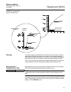
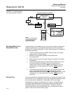
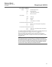
Figure 2-7 illustrates the Rosemount 3051N transmitter data flow. This data
flow can be summarized in four major steps:
1. A change in pressure is measured by a change in the sensor output
(Sensor Signal).
2. The sensor signal is converted to a digital format that can be
understood by the microprocessor (Analog-to-Digital Signal
Conversion).
3. Corrections are performed in the microprocessor to obtain a digital
representation of the process input (Digital PV).
4. The Digital PV is converted to an analog value (Digital-to-Analog
Signal Conversion).
Figure 2-7 also identifies the approximate transmitter location for each
calibration task. Note that the data flows from left to right, and a parameter
change affects all values to the right of the changed parameter.
Not all calibration procedures should be performed for each Rosemount
3051N transmitter. In addition, some procedures are appropriate for bench
calibration but should not be performed during field calibration. Table 2-2
identifies the recommended calibration procedures for each type of
Rosemount 3051N transmitter for both bench and field calibration.