


Reference Manual
00809-0100-4808, Rev CA
June 2008
Rosemount 3051N
3-12
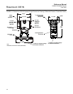
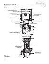
Process Connections Rosemount 3051N connections on the transmitter flange are
1
/4–18 NPT. Use
your plant-approved lubricant or sealant when making the connections. The
end-user is responsible for the qualification of the threaded seal interface on
the transmitter’s
1
/4-18 NPT connections.
Do not attempt to loosen or remove the flange bolts while the transmitter is
in service.
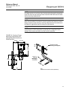
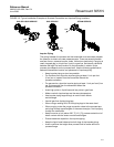
Housing Rotation The electronics housing can be rotated up to 180 degrees (left or right) to
improve field access or to better view the optional LCD meter. To rotate the
housing, perform the following procedure:
1. Loosen the housing rotation set screw using a
9
/64-in. hex wrench.
2. Turn the housing up to 180 degrees to the left or right of its original (as
shipped) position. Do not rotate the housing more than 180 degrees.
Over-rotation will sever the electrical connection between the
sensor module and the electronics module.
3. Retighten the housing rotation set screw.
ELECTRICAL
CONSIDERATIONS
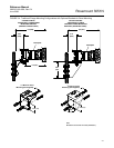
The transmitter terminal block is in the compartment of the electronics
housing labeled “FIELD TERMINALS.” The other compartment contains the
transmitter electronics module. Connections for the HART-based
communicator are attached beneath the terminal screws on the terminal
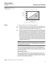
block. Figure 3-7 shows power supply load limitations for the transmitter.
Power Supply 4–20 mA Transmitters
The dc power supply should provide power with less than 2 percent ripple.
The total resistance load is the sum of the resistance of the signal leads and
the load resistance of the controller, indicator, and related pieces. Note that
the resistance of intrinsic safety barriers, if used, must be included.
NOTE
A minimum loop resistance of 250 ohms is required to communicate with a
HART-based communicator. With 250 ohms of loop resistance, the
transmitter will require a minimum of 16 volts to output 20 mA. If a single
power supply is used to power more than one Rosemount 3051N transmitter,
the power supply used, and circuitry common to the transmitters, should not
have more than 20 ohms of impedance at 1200 Hz. For additional details, see
Figure 3-7 "Power Supply Load Limitations."
See “Safety Messages” on page 3-1 for warning information.