


Reference Manual
00809-0100-4808, Rev CA
June 2008
Rosemount 3051N
6-2
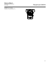
The meter features a two-line display with five digits for reporting the process
variable on the top line and six characters for displaying engineering units on
the bottom line. The LCD meter can also display flow and level scales. The
meter uses both lines to display diagnostic messages. The meter can be
configured to display the following information:
• engineering units
• percent of range
• user-configurable LCD scale
• alternating between any two of the above
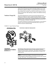
Custom Meter
Configuration
The user-configurable scale is a feature that enables the LCD meter to
display flow, level, or custom pressure units. The meter can be configured
using a HART Communicator (see Table A-1 on page A-4).
The user-configurable scale feature can define:
• decimal point position
• upper range values
• lower range values
• engineering units
• transfer function
To configure the meter with a HART communicator, perform the
following procedure:
1. Connect the communicator to the transmitter. Before connecting a
communicator in an explosive atmosphere, make sure the instruments in
the loop are installed according to intrinsically safe or nonincendive field
wiring practices.
2. From the ONLINE screen, select 1Device Setup, 3 Basic Setup, 7 Meter
Options, 2 Custom Meter Setup.
3. To specify decimal point position:
a. Select 1 Sel dec pt pos. Choose the decimal point representation
that will provide the most accurate output for your application. For
example, when outputting between 0 and 75 GPM, choose XX.XXX.
b. Go to Step 8.
4. To specify a custom upper range value:
a. Select 2 CM Upper Value. Type the value that you want the
transmitter to read at the 20 mA point.
b. Go to Step 8.
5. To specify a custom lower range value:
a. Select 3 CM Lower Value. Type the value that you want the
transmitter to read at the 4 mA point.
b. Go to Step 8.
6. To define custom units:
a. Select 4 CM Units. Enter the custom units (five characters
maximum) that you want the meter to display.
b. Go to Step 8.
7. To choose the transmitter transfer function for the meter:
See “Safety Messages” in Section 6 for warning information.
HART Comm 1, 3, 7, 2