


Reference Manual
00809-0100-4808, Rev CA
June 2008
3-9
Rosemount 3051N
Mounting The Rosemount 3051N Pressure Transmitter weighs approximately 6.0 lb
(2,7 kg) without additional options. For complete weight information, including
options, see “Physical Specifications” in Section 5. Optional mounting
brackets available with the Rosemount 3051N allow mounting to a panel or
wall. The B4 Bracket Option for use with the Coplanar flange is 316 SST and
provided with 316 SST bolts.
Bracket option B2 is a polyurethane painted carbon steel bracket designed for
use in panel mounting the traditional flange (H2). The B2 bracket is provided
with carbon steel bolts.
Bracket option BS is a 316LSST bracket provided with carbon steel bolts that
is designed for use in panel mounting the traditional flange (option code H2).
It is the same bracket used on other Rosemount Nuclear Instruments, Inc.
nuclear qualified transmitters, including the Rosemount 1153 Series D and
Rosemount 1154.
Bracket option PM is a SST pipe mount bracket assembly designed for use in
pipe mounting the traditional Flange (option code H2). It is the same bracket
used on other Rosemount Nuclear Instruments, Inc. nuclear qualified
transmitters, including the Rosemount 1154 Series H.
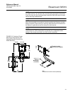
When installing the transmitter to the mounting bracket, torque the mounting
bolts to 21 ft.-lbs.
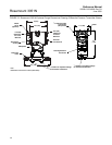
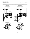
Dimensions and typical mounting configurations are contained in this section.
NOTE
The transmitter is calibrated in an upright position at the factory. If you mount
the transmitter in any other position, the zero point will shift by an amount
equivalent to the liquid head caused by the varied mounting position. To reset
the zero point, refer to “Sensor Trim” in Section 2.
Mounting Requirements
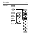
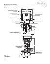
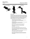
Refer to Figure 3-6 for examples of the following mounting configurations:
Liquid Flow Measurement
• Place taps to the side of the line to prevent sediment deposits on the
transmitter’s process isolators.
• Mount the transmitter beside or below the taps so gases can vent into
the process line.
• Mount drain/vent valve upward to allow gases to vent.
Gas Flow Measurement
• Place taps in the top or side of the line.
• Mount the transmitter beside or above the taps so liquid will drain into
the process line.
Steam Flow Measurement
• Place taps to the side of the line.
• Mount the transmitter below the taps to ensure that the impulse piping
will stay filled with condensate.
• Fill impulse lines with water to prevent the steam from contacting the
transmitter directly and to ensure accurate measurement start-up.