


Reference Manual
00809-0100-4808, Rev CA
June 2008
2-13
Rosemount 3051N
Transmitter Test The transmitter Self Test command initiates a more extensive diagnostics
routine than that performed continuously by the transmitter. The transmitter
test routine can quickly identify potential electronics problems. If the
transmitter test detects a problem, messages to indicate the source of the
problem are displayed on the communicator screen.
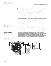
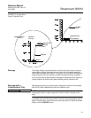
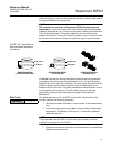
Loop Test The Loop Test command verifies the output of the transmitter, the integrity of
the loop, and the operations of any recorders or similar devices installed in the
loop. To initiate a loop test, perform the following procedure:
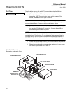
1. Connect a reference meter to the transmitter. To do so, either connect
the meter to the test terminals on the transmitter terminal block, or
shunt the power to the transmitter through the meter at some point in
the loop.
2. From the ONLINE screen, select 1 Device Setup, 2 Diagnostics and
Service, 2 Loop Test, to prepare to perform a loop test.
3. Select OK after you set the control loop to manual (see “Setting the
loop to Manual”). The communicator displays the loop test menu.
4. Select a discreet milliamp level for the transmitter to output. At the
CHOOSE ANALOG OUTPUT prompt, select 1 4mA, 2 20mA, or
select 3 other to manually input a value. IF
you are performing a loop
test to verify the output of a transmitter, THEN
enter a value between
4 and 20 mA. IF
you are performing a loop test to verify the
transmitter alarm levels, THEN
enter the milliamp value representing
an alarm state (see Table 2-1).
5. Check the electrical current meter installed in the test loop to verify
that it reads the value you commanded the transmitter to output. IF
the readings match, THEN
the transmitter and the loop are
configured and functioning properly. IF
the readings do not match,
THEN
you may have the current meter attached to the wrong loop,
there may be a fault in the wiring or elsewhere in the loop, the
transmitter may require an output trim, or the electrical current meter
may be malfunctioning.
After completing the test procedure, the display returns to the loop test screen
and allows you to choose another output value or to exit loop testing.
NOTE
If the HART Communicator is disconnected from the process loop or loses
power prior to exiting loop testing, output will remain fixed at the loop test
value.
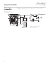
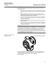
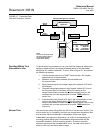
CALIBRATION Calibrating a smart transmitter is different from calibrating an analog
transmitter. The one-step calibration process of an analog transmitter is done
in three steps with a smart transmitter:
• Rerange—sets the 4 and 20 mA points at the desired pressures;
• Sensor Trim—Adjusts the position of the factory characterization curve
to optimize the transmitter performance over a specified pressure
range or to adjust for mounting effects
• Analog Output Trim—Adjusts the analog output to match the plant
standard or the control loop.
HART Comm. 1, 2, 1, 1
HART Comm. 1, 2, 2