


Reference Manual
00809-0100-4808, Rev CA
June 2008
Rosemount 3051N
3-4
GENERAL
CONSIDERATIONS
Measurement accuracy depends upon proper installation of the transmitter
and impulse piping. Mount the transmitter close to the process and use a
minimum of piping to achieve best accuracy. Keep in mind the need for easy
access, personnel safety, practical field calibration, and a suitable transmitter
environment. Install the transmitter to minimize vibration, shock, and
temperature fluctuation.
Special Draft Range
Considerations
Installation
It is best to mount the transmitter with the isolating diaphragms parallel to the
ground. Installing the transmitter in this way reduces oil head effect and
provides for optimal temperature performance.
Be sure the transmitter is securely mounted. Tilting of the transmitter may
cause a zero shift in the transmitter output.
Reducing Process Noise
It is often difficult to isolate the actual process variable from process noise in
draft range applications. Pressure fluctuations and air currents can make
accurate draft range measurements difficult to obtain.
There are two recommended methods of reducing process noise: output
damping and, in gage applications, reference side filtering.
Output Damping
The output damping for the Rosemount 3051ND0 is factory set to 3.2
seconds as a default. If the transmitter output is still noisy, increase the
damping time. If faster response is needed, decrease the damping time.
Damping adjustment information is available in Section 2: Transmitter
Functions.
Reference Side Filtering
In gage applications it is important to minimize fluctuations in atmospheric
pressure to which the low side isolator is exposed. One method of reducing
fluctuations in atmospheric pressure is to attach a length of tubing to the
reference side of the transmitter to act as a pressure buffer. Another method
is to plumb the reference side to a chamber that has a small vent to
atmosphere. If multiple draft transmitters are being used in an application, the
reference side of each device can be plumbed to a chamber to achieve a
common gage reference.
IMPORTANT
Install the enclosed pipe plug in unused conduit openings with a minimum of
five threads engaged to comply with explosion proof requirements.
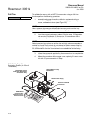
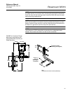
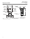
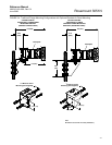
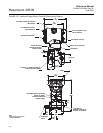
MECHANICAL
CONSIDERATIONS
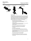
The following figures show dimensional drawings and installation examples of
the Rosemount 3051N transmitters, including mounting brackets.
NOTE
For Rosemount 3051ND0 and 3051ND1, mount the transmitter solidly to
prevent tilting. A tilt in the physical transmitter may cause a zero shift in the
transmitter output.