


Reference Manual
00809-0100-4808, Rev CA
June 2008
3-11
Rosemount 3051N
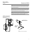
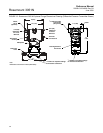
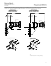
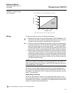
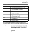
FIGURE 3-6. Typical Installation Examples to Illustrate Transmitter and Impulse Piping Locations.
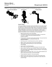
Impulse Piping
The piping between the process and the transmitter must accurately transfer
the pressure to obtain accurate measurements. There are several possible
sources of error: pressure transfer, leaks, friction loss (particularly if purging is
used), trapped gas in a liquid line, liquid in a gas line, and density variations
between the legs.The best location for the transmitter in relation to the
process pipe depends on the process itself. Use the following guidelines to
determine transmitter location and placement of impulse piping:
• Keep impulse piping as short as possible.
• For liquid service, slope the impulse piping at least 1 inch per foot
(8 cm per m) upward from the transmitter toward the
process connection.
• For gas service, slope the impulse piping at least 1 inch per foot (8 cm
per m) downward from the transmitter toward the
process connection.
• Avoid high points in liquid lines and low points in gas lines.
• Make sure both impulse legs are the same temperature.
• Use impulse piping large enough to avoid friction effects
and blockage.
• Vent all gas from liquid piping legs.
• When using a sealing fluid, fill both piping legs to the same level.
• When purging, make the purge connection close to the process taps
and purge through equal lengths of the same size pipe. Avoid purging
through the transmitter.
• Keep corrosive or hot (above 250 °F [121 °C]) process material out of
direct contact with the sensor module and flanges.
• Prevent sediment deposits in the impulse piping.
• Keep the liquid head balanced on both legs of the impulse piping.
• Avoid conditions that might allow process fluid to freeze within the
process flange.
Flow
Flow
Flow
GAS OR LIQUID SERVICE GAS SERVICE STEAM SERVICE