


Reference Manual
00809-0100-4808, Rev CA
June 2008
2-5
Rosemount 3051N
To commission on the bench, connect the transmitter and the communicator
as shown in Figure 2-3. Make sure the instruments in the loop are installed in
accordance with intrinsically safe or nonincendive field wiring practices before
connecting a communicator in an explosive atmosphere. Connect the
communicator leads at any termination point in the signal loop. It is most
convenient to connect them to the terminals labeled “COMM” on the terminal
block. Connecting across the “TEST” terminals will prevent successful
communication. To avoid exposing the transmitter electronics to the plant
environment after installation, set all transmitter jumpers during the
commissioning stage on the bench.
For 4–20 mA transmitters, you will need a power supply capable of providing
10.5 to 55 V dc at the transmitter, and a meter to measure output current. To
enable communication, a resistance of at least 250 ohms, but within the
transmitter load limitations (see Figure 3-7 “Power Supply Load Limitations.”
in Section 3) must be present between the communicator loop connection and
the power supply. Do not use inductive-based transient protectors with the
Rosemount 3051N.
Setting the Loop to
Manual
Whenever you are preparing to send or request data that would disrupt the
loop or change the output of the transmitter, you must set your process
application loop to manual. The HART Communicator will prompt you to set
the loop to manual when necessary. Keep in mind that acknowledging this
prompt does not set the loop to manual. The prompt is only a reminder; you
have to set the loop to manual yourself as a separate operation.
Wiring Diagrams
(Bench Hook-up)
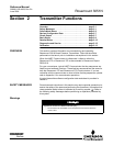
Connect the bench equipment as shown in Figure 2-3 and turn on the
HART-based Communicator by pressing the ON/OFF key. The communicator
will search for a HART-compatible device and will indicate when the
connection is made. If the communicator fails to connect, it will indicate that
no device was found. If this occurs, refer to Section 4: Troubleshooting.
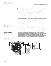
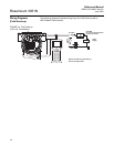
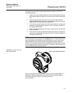
FIGURE 2-3. Bench Hook-up
(4–20 mA Transmitters).
See “Safety Messages” on page 2-1 for warning information.
24 V dc
Supply
R
L
≥250Ω
Current
Meter