


Reference Manual
00809-0100-4808, Rev CA
June 2008
Rosemount 3051N
3-14
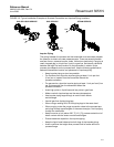
Grounding the
Transmitter Case
The transmitter case should always be grounded in accordance with national
and local electrical codes. The most effective transmitter case grounding
method is direct connection to earth ground with minimal impedance.
Methods for grounding the transmitter case include:
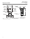
• Internal Ground Connection: The Internal Ground Connection screw
is inside the FIELD TERMINALS side of the electronics housing. This
screw is identified by a ground symbol ( ), and is standard on all
Rosemount 3051N transmitters.
• External Ground Assembly: This assembly is included as standard
with the transient protection terminal block (T1) included with the
Rosemount 3051N
NOTE
Grounding the transmitter case using the threaded conduit connection may
not provide a sufficient ground. The standard transient protection terminal
block (T1) does not provide transient protection unless the transmitter case is
properly grounded. Use the above guidelines to ground the transmitter case.
Do not run the transient protection ground wire with signal wiring as the
ground wire may carry excessive current if a lightning strike occurs.
ENVIRONMENTAL
CONSIDERATIONS
The following guidelines can help optimize transmitter performance. Mount
the transmitter to minimize ambient temperature changes, vibration,
mechanical shock, and to avoid external contact with corrosive materials.
“Specifications and Reference Data” in Section 5 lists transmitter temperature
operating limits.
Access Requirements When choosing an installation location and position, take into account the
need for access to the transmitter.
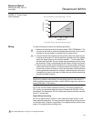
Process Flange Orientation
Mount the process flanges with sufficient clearance for process connections.
For safety reasons, place the drain/vent valves so the process fluid is directed
away from technicians when the vents are used. In addition, consider the
possible need for a testing or calibration input.
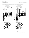
Housing Rotation
See “Housing Rotation” in Section 3.
Terminal Side of Electronics Housing
Mount the transmitter so that the terminal side is accessible. A 0.75-inch (19
mm) clearance is required for cover removal. Use a conduit plug on the
unused side of the conduit opening.
Circuit Side of Electronics Housing
Provide 0.75 inches (19 mm) clearance for cover removal. Three inches of
clearance is required for cover removal if a meter is installed.
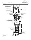
Exterior of Electronics Housing
The integral span and zero adjustments are located under the label plate on
the top of the transmitter. Allow a minimum of 1.0 inch of clearance above the
transmitter if you intend to use the integral zero and span adjustments.
Cover Installation Always install the electronics housing covers metal-to-metal to ensure a
proper seal.