


Reference Manual
00809-0100-4808, Rev CA
June 2008
Rosemount 3051N
2-16
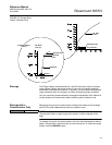
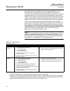
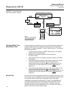
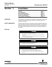
FIGURE 2-7. Transmitter Data
Flow with Calibration Options.
Deciding Which Trim
Procedure to Use
To decide which trim procedure to use, you must first determine whether the
analog-to-digital section or the digital-to-analog section of the transmitter
electronics is in need of calibration. To do so, refer to Figure 2-7 and perform
the following procedure:
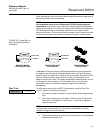
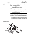
1. Connect a pressure source, a HART Communicator, and a digital
readout device to the transmitter.
2. Establish communication between the transmitter and
the communicator.
3. Apply pressure equal to the upper range point pressure (100 inH
2
0,
for example).
4. Compare the applied pressure to the Process Variable (PV) line on
the Communicator On-line Menu. IF
the PV reading on the
communicator does not match the applied pressure, and you are
confident that your test equipment is accurate, THEN
perform a
sensor trim.
5. Compare the Analog Output (AO) line on the communicator on-line
menu to the digital readout device. IF
the AO reading on the
communicator does not match the digital readout device, and you are
confident that your test equipment is accurate, THEN
perform an
output trim.
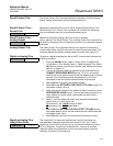
Sensor Trim You can trim the sensor using either the full trim or the zero trim function. The
trim functions vary in complexity, and their use is application-dependent. Both
trim functions alter the transmitter’s interpretation of the input signal.
A zero trim is a single-point adjustment. It is useful for compensating for
mounting position effects and is most effective when performed with the
transmitter installed in its final mounting position. Since this correction
maintains the slope of the characterization curve, it should not be used in
place of a full trim over the full sensor range.
Transmitter Electronics Module
Microprocessor
Digital PV
Sensor
Input Device
Output Device
20.00 mA
3051:PT-4001
1 ➡ Device Setup
Online
2 PV 100.00 inH2O
3 AO 20.00 mA
4 LRV 0.00 inH2O
5 URV 100.00 inH2O
Transmitter Ranged 0 to 100 inH
2
O
Input
Pressure
Sensor
Signal
Analog Output
HART
Communicator
NOTE
Value on PV line should equal
the input pressure. Value on
AO line should equal the
output device reading.