


68
Service
Removing and Replacing Assemblies
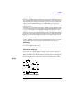
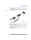
CAUTION Note where the two pins at the rear of the top cover enter the holes in the PC assembly.
Position the cable wires away from these two areas. When the bottom cover is closed,
part of it will pinch wires that are laying over these areas.
b Insert the pins at the front of the bottom cover into the holes at the front of the top
cover.
c Close the covers together and fasten with the probe clamp ring. If the covers do not
fit together tightly and easily, check for pinched wires (see caution above).
Probe Adapters
Use the following procedure to disassemble the probe adapters. The adapter housing
consists of two plastic parts, one of which slides into the other. The parts are held
together by the spring effect of two plastic tabs on the inner part.
Mechanically, the ac adapter is about the same as the 10x and 100x attenuator adapters.
The attenuator adapters have an extra ground connector which connects the substrate
ground to the thumbwheel screw and plating inside the housing.
Disassemble Adapter
1
Remove the probe tip caps and probe tips from the adapter input.
2 Hold the adapter in one hand taking care not to block the output end of the
adapter (the end which attaches to the probe).
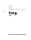
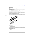
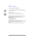
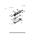
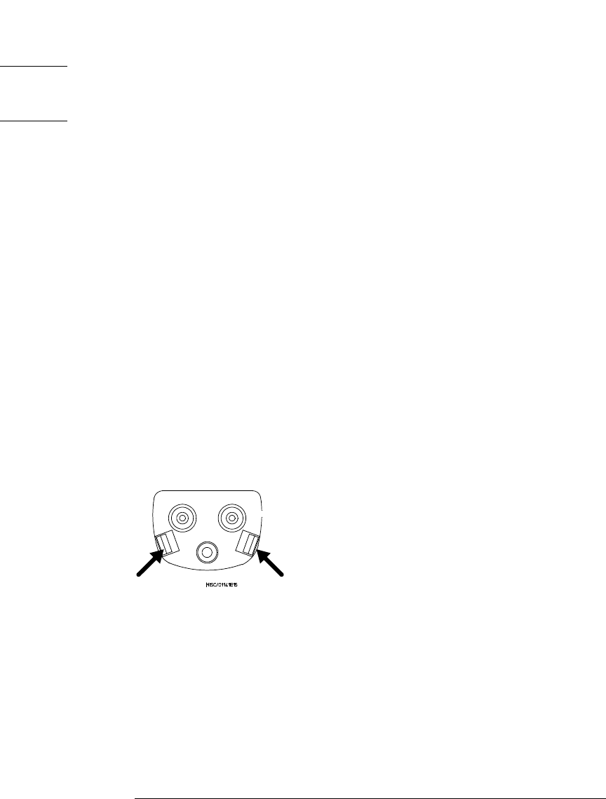
3 Note the view of the input end of the adapter in the figure below. The arrows
indicate the holding tabs.
Figure 3-9
Disassembling Adapters
4 With the thumb and forefinger, squeeze the tabs together, as indicated by the
arrows. Simultaneously, push the tabs into the outer housing so the inner
housing begins to slide out.
5 While holding the outer housing, push back against the thumbwheel until the
inner housing can be grasped and removed.
Reassemble Adapter
Reassembling the adapter is slightly harder because you have to align the connector pins
and thumbwheel screw, while sliding the inner housing and outer housing together.
1
Be sure the input connectors and output pins are present and seated on the
substrate or PC board.