


42
Calibration Tests and Adjustment
Adjustment Procedure
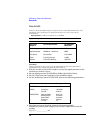
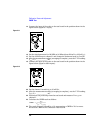
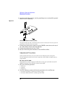
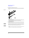
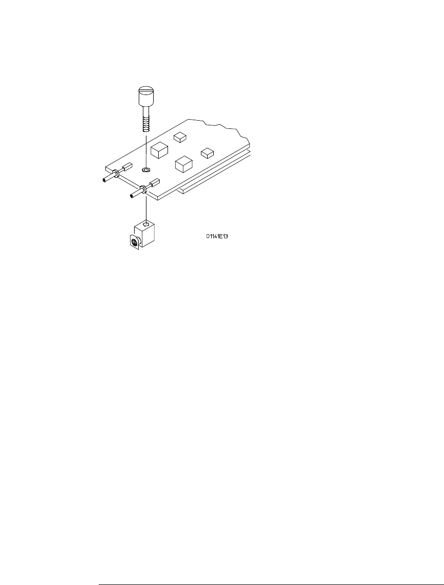
6 As shown in the figure below, use the grounding screw to reinstall the ground
block on the PC assembly.
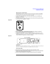
Figure 2-13
Attaching Ground Block to Probe PC Assembly
The ground block provides a mechanical and electrical connection when the probe PC
assembly is connected to the test board.
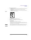
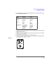
7 Connect the probe power connector to the PROBE connection on the rear of
the 1142A Probe Control and Power Module.
8 Connect the mains power to the 1142A.
9 Set the 1142A front panel switches to Local and Zero offset.
Adjustment Procedure
Unless specified elsewhere, the procedures must be followed in the order given.
The only adjustment which may be done separately is HF COMP, the high-frequency
compensation.
HF Gain and HF CMRR
This adjustment sequence adjusts the HF Gain for unity gain at 500 kHz and the HF
CMRR for minimum with a 500 kHz common mode signal.
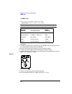
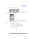
1
Set up the function generator.
• Sine wave
• 500 kHz
•600 mV
p-p
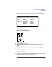
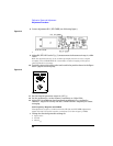
2 Use BNC cables to connect the function generator to the oscilloscope.
• Generator OUTPUT to oscilloscope channel 1 input
• Generator TRIG OUTPUT to oscilloscope EXT TRIG