


21
Operating the Probe
Recommended Test Equipment
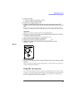
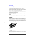
To use ac coupling:
1
Attach the ac coupling adapter to the input of the probe or the input of the
attenuator adapter.
2 On the 1142A, press Local and Zero offset.
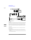
Remote operation
For automatic test applications, the coupling and offset functions provided by the 1142A
Probe Control and Power Module can be remotely controlled through a connector on the
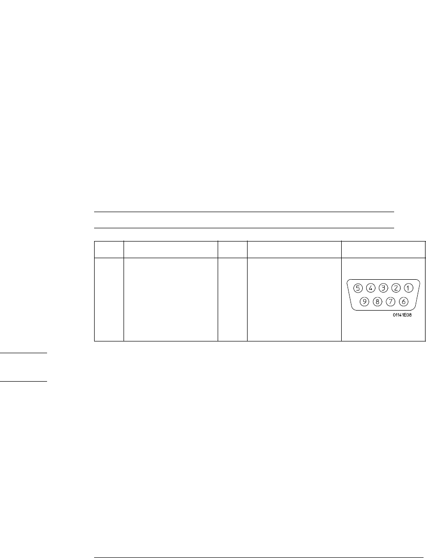
rear panel of the module. The connection is through a standard 9-pin female
D-subminiature connector. This style is the same as that used on some personal
computer monitor cables, which provides an economical way to connect the 1142A to
the controller interface on an automatic test system.
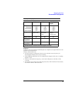
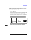
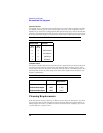
The following table gives the connections.
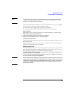
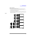
Remote Input Connections
NOTE To minimize dc offset errors and potential noise coupling, electrically isolate all
connections between the Remote Input connector and the controlling system.
Pin Function Pin Function Connector
1 Function Select 1 (A1R) 6 Function Select 0 (A0R)
2 Digital common 7 N.C.
3N.C. 8N.C.
4 External offset common 9 External offset
5 Shield