


47
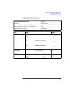
Calibration Tests and Adjustment
Adjustment Procedure
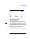
High Frequency Compensation
This adjustment sequence continues from the Low Frequency Response and CMRR
adjustment. However, it can be done separately if the probe meets all specifications
except bandwidth. Adjust R13 for unity gain at 200 MHz.
1 Connect the signal generator to the test board and set it for 200 MHz and
300mV
p-p
(107 mV
rms
).
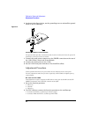
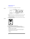
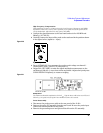
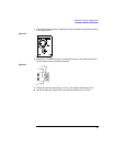
2 Carefully connect the input of the probe to the test board in the position shown
in the figure below (signal to + input).
Figure 2-20
Signal to + input
3 Press AUTOSCALE, then measure the peak-to-peak voltage on channel 1
(Press SHIFT (blue), press V P-P, then press 1).
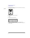
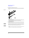
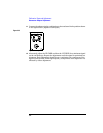
4 Adjust R13 (HF COMP) to make the signal amplitude measurement on the
oscilloscope 300 mV
p-p
, or as close to that as possible. Adjust slowly and press
CLEAR DISPLAY frequently to restart averaging.
Figure 2-21
R13 Adjustment
The minimum allowable amplitude is 212 mV
p-p
. Typical values will be between 275 and
325 mV
p-p
. the probe needs repair if the minimum cannot be reached.
Probe Reassembly
1
Disconnect the probe power cable at the rear panel of the 1142A
2 Remove the probe PC assembly from the test board. Be sure the probe input
connectors remain attached to the probe.
3 Remove the grounding screw and ground block from the PC assembly.