


11
Operating the Probe
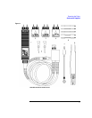
Recommended Test Equipment
WARNING Before connecting this instrument, the protective earth terminal of the instrument must
be connected to the protective conductor of the (Mains) power cord. The Mains plug
must be inserted in a socket outlet provided with a protective each contact. The
protective action must be negated by the use on an extension cord (power cable)
without a protective conductor (grounding). Grounding one conductor of a two-
conductor outlet does not provide an instrument ground.
This instrument is provided with a three-wire power cable. When connected to an
appropriate ac power outlet, this cable grounds the instrument cabinet. The type of
power cable plug shipped with the instrument depends on the country of destination.
The 1142A Power Control and Power Module does not have a power switch. A power
switch is not required because of the low mains power requirement.
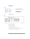
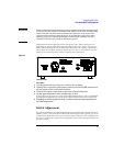
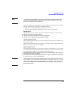
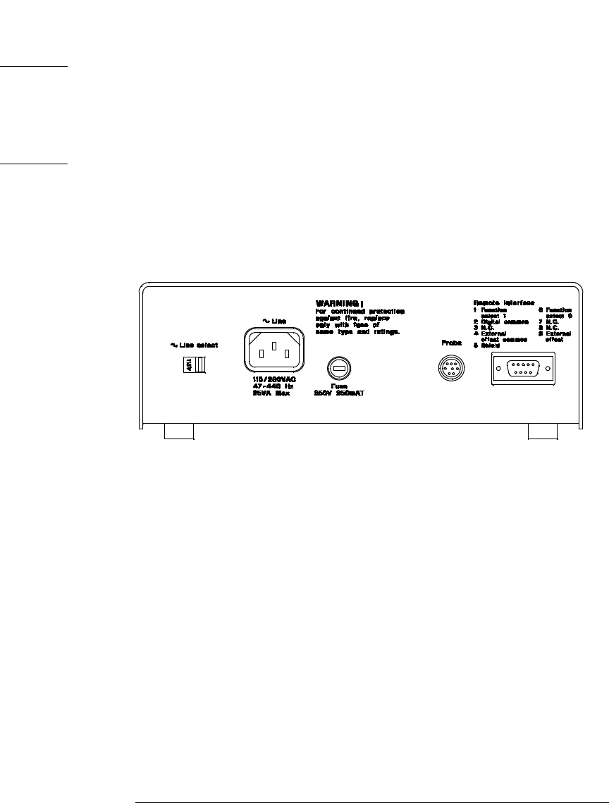
Figure 1-4
1142A Rear Panel
Procedure
1
Use the power cord to connect the 1142A to the ac mains.
2 Connect the 1141A probe cable power connector to the PROBE connector on
the rear panel of the 1142A power module.
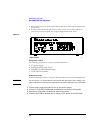
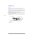
3 Connect the output of the probe to the input of the oscilloscope.
4 Set the input impedance of the oscilloscope to 50 Ω.
If the oscilloscope does not have a selectable 50 Ω input impedance, connect a 50 Ω BNC
feedthrough termination between the probe output and the input of the oscilloscope.
5 If making an initial equipment setup, continue with the initial adjustment in
the following section.
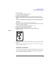
Initial Adjustment
For a given combination of 1141A Differential Probe and 1142A Probe Control and Power
Module, you may want to adjust the Offset Null and DC Reject Gain. Typically, you need
to make these adjustments only once, before the probe is first used. You can make them
any time to optimize the system. These adjustments do not affect the specifications of
the probe system.