


38
Calibration Tests and Adjustment
CMRR Test
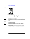
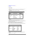
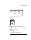
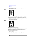
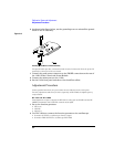
15 Connect the input of the probe to the test board in the position shown in the
figure below (signal to + input).
Figure 2-11
Signal to + input
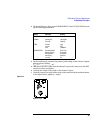
16 Set the signal generator for 100 MHz at 0.0 dBm (about 224 mV
rms
, 632 mV
p-p
).
17 Set the oscilloscope to channel 1 and change the horizontal scale to 5 ns/div.
18 After the measurement settles (averaging is complete), note the V P-P reading.
V
p-p
(1) = _____________ mV
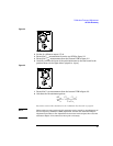
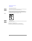
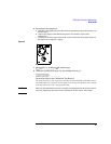
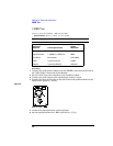
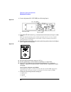
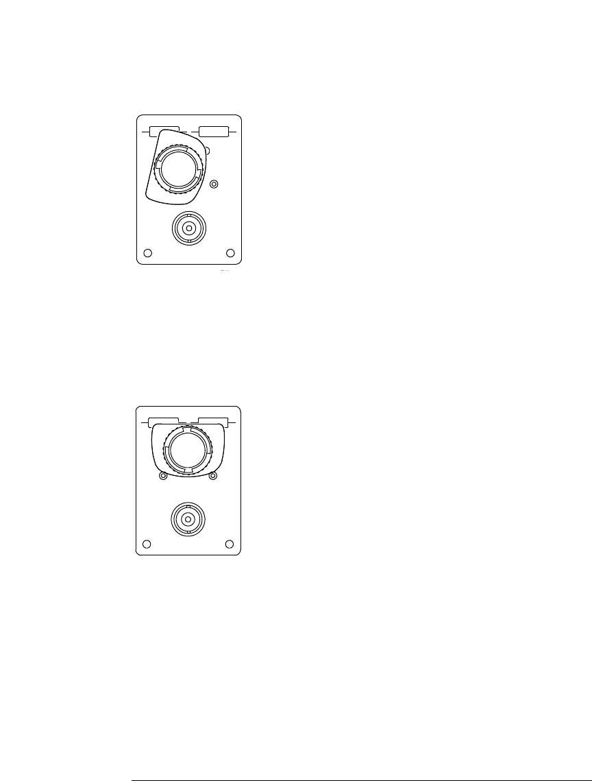
19 Connect the input of the probe to the test board in the position shown in the
figure below (signal to both inputs).
Figure 2-12
Signal to both input
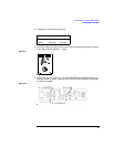
20 Set the channel 1 sensitivity to 10 mV/div.
21 After the measurement settles (averaging is complete), not the V P-P reading.
V
p-p
(2) = _____________ mV
22 Disconnect the probe amp from the test board and measure V
noise pp
on
channel 1.
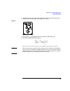
23 Calculate the CMRR result as follows
24 The result in step 21 should be ≥ 10, representing a CMRR of 10:1 or more.
Record the CMRR in the Calibration Test Record.
CMRR
V
pp
1
V
pp
2
V
noisepp
–
-------------------------------------=