


15
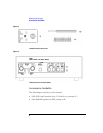
Operating the Probe
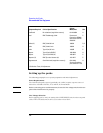
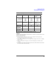
Recommended Test Equipment
Note Use extension leads and similar connection accessories carefully. Extension leads
compromise the high-frequency specifications of the probe. CMRR is particularly
sensitive to unbalanced input parameters.
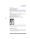
To prevent pickup of stray fields when you use extension lead, either the ones supplied
with the 1141A or others, dress them carefully as follows:
• Connect the leads at right angles to the circuitry under test.
• Keep the leads as parallel as possible before they connect to the probe.
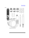
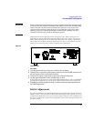
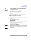
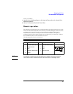
Mini-Grabbers
Mini-grabbers can be attached to the probe or adapter through the extension leads.
1
Remove the probe tip caps and tips.
2 Attach the extension leads to the probe or adapter.
3 Attach the mini-grabbers to the extension leads.
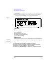
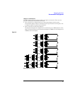
Circuit Connector Posts
These 0.025-inch square posts can be used to connect either directly to the probe or to
the extension leads.
Solder the posts directly into your circuitry or use them to make extension leads that
plug into the inputs of the probe or adapters.
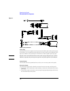
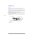
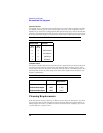
Shielded Signal Leads
The shielded signal leads allow connection to points in a circuit that are up to 10 inches
apart. The leads are shielded to within approximately 1/2 inch of the end of the lead so
they minimize pick-up due to stray fields from adjacent circuitry.
1
Connect the end with the ground connector to the probe pins and ground of
the differential probe or adapter.
2 Connect the free ends of the leads to 0.025-inch square or 0.030-inch round pins
in your circuitry or to the mini-grabbers.
Note Each lead has an input capacitance of approximately 15 pF. This capacitance may limit
the bandwidth of your measurement (depending on the impedance of the circuit). Also,
CMRR may be affected because of slight differences between the input capacitance of
the two leads. CMRR is also affected by differences in impedance between the two
measurements points.