


66
Service
Removing and Replacing Assemblies
Removing and Replacing Assemblies
This section contains procedures for the removal and replacement of major assemblies.
CAUTION Never remove or install any assembly with the instrument power ON. Component
damage can occur.
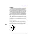
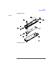
Differential Probe
Use the following procedure to remove and replace the amplifier PC board in the
differential probe.
CAUTION ELECTROSTATIC DISCHARGE can damage electronic components. Use grounded
wrist straps and mats when servicing the probe.
CAUTION Handle the differential probe carefully once it has been disassembled. If unsupported,
the weight of the cable can put strain on the PC board.
Disassemble Probe
1
Remove the probe tip caps and probe tips.
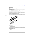
2 Loosen the probe clamp ring at the cable end of the probe (1/4 turn counter-
clockwise) and slide it down the cable.
3 Remove the bottom cover.
a At the cable end of the probe, separate the covers about one centimeter (1/2 inch).
b Slide the bottom cover toward the cable end of the probe until the locator pins at
the probe input clear the holes. Then, remove the cover.
Note the way the cable strain relief is keyed and held at the rear of the top cover.
4
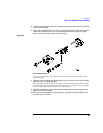
Remove the probe top cover.
The ground screw passes through the top cover and PC board and screws into the ground
block.
a Remove the ground screw on the top of the probe.
At the cable end, the PC board fits over the pins in the top cover.
b Lift the board off of the pins and slide it in the direction of the cable until the input
connectors clear the front of the probe.
5 Un-solder the two connections where the coaxial output cable connects to the
PC board.
6 Disconnect the cable connector from the probe PC board.