


20
Operating the Probe
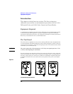
Recommended Test Equipment
To use dc reject:
1
Remove the ac adapter if it is installed.
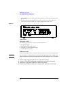
2 On the front panel of the 1142A, press Local.
3 Under DC Reject on the front panel, press 5.0 Hz or 0.5 Hz individually, or
5.0 Hz and 0.5 Hz simultaneously to get 0.05 Hz.
Within the frequency and voltage characteristics noted elsewhere in this manual, low
frequencies are nulled from the input signal.
Offset
Offset is the best method to use when the low-frequency corners associated with dc
reject and the ac adapter interfere with the measurement.
The key characteristics are:
• The user manually null the dc component with the offset adjustment.
• Offset is dc coupled so there is no low frequency roll-off.
• Probe CMRR specifications are not compromised as happens when the ac coupling
adapter is used.
• The voltage offset range is ±20 V with the probe alone, ±200 V with the 10x attenuator,
and ±500 V with the 100x attenuator. (With the 100x attenuator, the offset range is
restricted by the maximum input voltage rating rather than the operating range of
the offset).
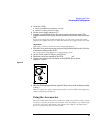
To use offset:
1
Remove the ac adapter if it is installed.
2 On the front panel of the 1142A, press Local and Variable offset.
3 Adjust the Coarse and Fine Variable Offset until the signal is displayed on the
screen of the oscilloscope.
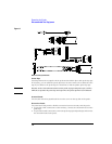
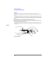
ac Adapter
The ac adapter must be used when the dc component of the signal exceeds the operating
range of the dc reject or offset methods. The ac adapter block the dc and low frequency
component of the input by forming a high pass filter with the input impedance of the
probe or adapter.
The key characteristics are:
• The ac adapter safely blocks ±200 Vdc when attached directly to the probe or
±500 Vdc when attached to a 10x or 100x adapter.
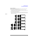
• The probe and adapters have different input impedances, so they have different low
frequency corners with the ac adapter. When the ac adapter is directly on the probe
the -3dB corner is 15 Hz. When the ac adapter is on an attenuator the corner is 1.5 Hz.
• The low-frequency CMRR when using the ac adapter is not as good as when using the
probe alone or the probe with a 10x or 100x adapter.
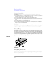
CAUTION If you measure a node having a high dc potential, the blocking capacitors in the ac
adapter will charge to that potential. After making such measurements, discharge the
capacitors by grounding both inputs of the ac adapter. This will prevent damage by a
high voltage discharge into sensitive circuitry when the next measurement is made.