


44
Calibration Tests and Adjustment
Adjustment Procedure
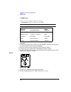
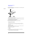
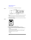
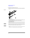
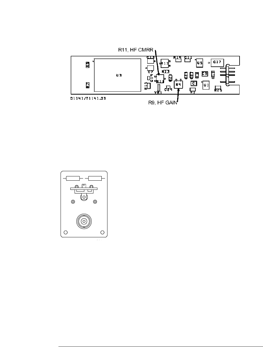
8 Center adjustment R11, HF CMRR (see following figure).
Figure 2-15
R11, HF CMRR Adjustment
9 Adjust R9, HF GAIN so the V
p-p
(1) measurement is the same as in step 4, within
±0.5%.
Make the adjustment slowly so the oscilloscope display has time to react to signal
averaging. Press CLEAR DISPLAY occasionally to restart averaging, which gives a
quicker indication of changes.
10
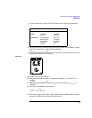
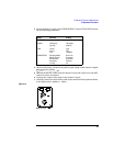
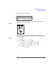
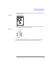
Carefully connect the probe to the test board in the position shown in the figure
below (signal to both inputs).
Figure 2-16
Signal to both inputs
11 Set the function generator output to 1.0 V
p-p
.
12 On the oscilloscope, set the channel 1 sensitivity to 1.00 mV/div.
13 Adjust R11 for minimum signal amplitude as shown in V
p-p
reading for
channel 1. Adjust R11 slowly and use CLEAR DISPLAY frequently to restart
averaging.
Low Frequency Response and CMRR
This adjustment sequence continues from the HF Gain and HF CMRR adjustments.
Adjust R14 and C4 for pulse response, and adjust C6 for low-frequency CMRR.
1
Change the function generator settings to:
• Square wave
• 2.5 kHz
•600 mV
p-p