


48
Calibration Tests and Adjustment
Adjustment Procedure
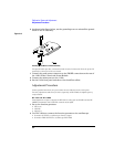
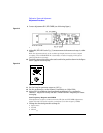
4 Assemble the PC assembly in the top cover.
The side of the PC assembly with the large hybrid is exposed when the assembly is in
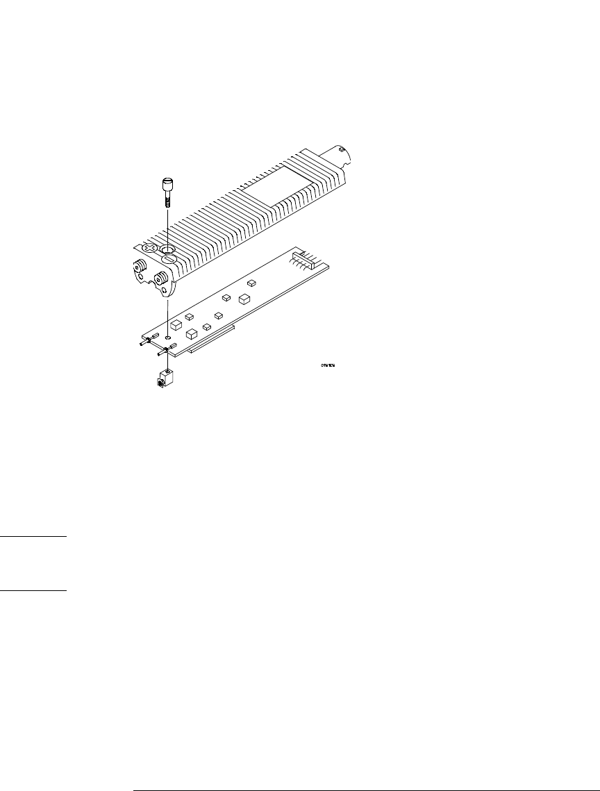
the top cover. The figure below shows how the top cover, PC board, and ground block
fit together.
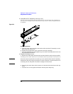
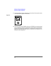
Figure 2-22
Reassembling the Probe
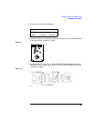
a
Insert the input connectors first, and seat the cable end of the PC assembly over the
pins at the rear of the cover.
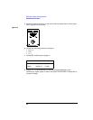
b Position the ground block at the center-front of the PC assembly.
c Insert the grounding screw through the top cover and PC assembly and screw it into
the ground block as shown.
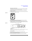
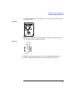
5 Replace the bottom cover.
a Position the cable strain relief and with one hand, hold the cable and top together.
The flange on the strain relief has a notch that fits around a protrusion in the top cover.
CAUTION Note where the two pins at the rear of the top cover enter the holes in the PC assembly.
Position the cable wires away from these two areas. Otherwise, when the bottom cover
is closed, part of it will pinch wires that are laying over these areas.
b Insert the pins at the front of the bottom cover into the holes at the front of the top
cover.
c Close the two covers together and fasten with the probe clamp ring.