


18
Operating the Probe
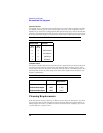
Recommended Test Equipment
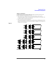
Connector Compatibility
The following are general connector characteristics for the probe, adapters, and
accessories.
• The female connectors on the probe, adapters, and other accessories are designed to
mate with 0.030-inch round or 0.0250-inch square pins.
• The probe, adapter, and extension lead pins are 0.030-inch round.
• The strip of circuit connection posts provided as an accessory has 0.025-inch square
pins.
• The mini-grabber has a 0.25-inch square pin.
• The ground connection at the end of the probe and adapters (where the adapters
fasten) accepts an M3 metric screw.
Test Board
The primary use of the test board is to apply test and calibration signals to the input of
the probe or adapters. Specific use of the test board is covered wherever it applies.
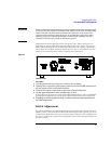
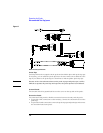
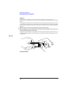
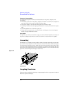
Grounding
Grounding is very important when probing circuitry. Improper grounding can increase
the common mode signal level. This reduces the effectiveness of the differential probe.
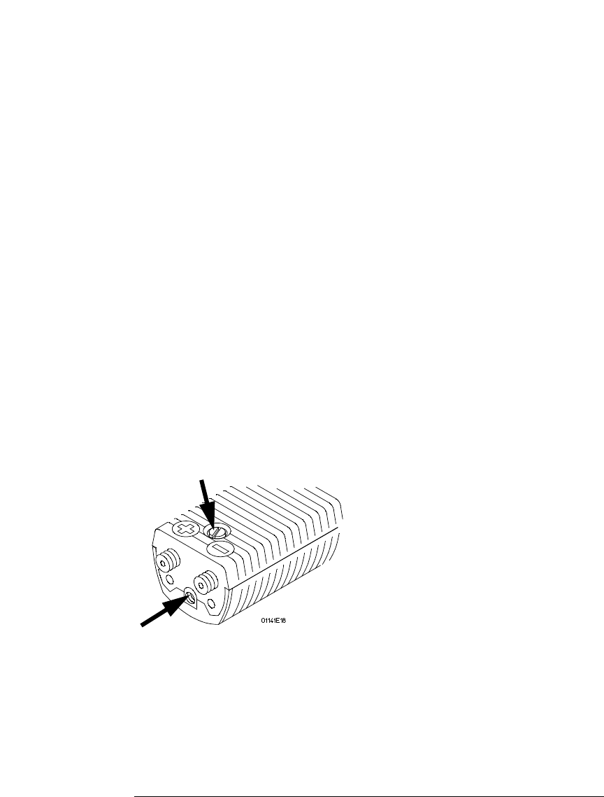
The mechanical connections at the input of the probe are ground for probe signals. The
screw where the ground lead attaches (see figure 1-7) fastens to this ground. Also, the
attenuator and ac adapter fasten to this ground through the screw connection and the
ground is carried through each adapter to its front.
Figure 1-10
Probe Grounds
Coupling Functions
There are three methods for blocking or compensating for the dc component of a signal.
Each has specific advantages.