


61
Service
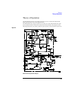
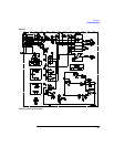
Theory of Operation
Offset Functions
There are two offset functions developed in the control module: variable offset and dc
reject. A variable offset voltage with coarse and fine adjustments can be selected by the
front panel controls. The offset level is buffered by U8 and selected by multiplexer U3
as the input to offset amp U7. The output of the offset amp is summed with the low-
frequency signal and feedback which gives dc coupling in the probe. Front panel
screwdriver adjustment Offset Null zeros the dc output from the probe when the dc input
and offset are zero.
For dc Reject, an output from the low-frequency amplifier in the probe (LFSIG) is used
to develop a voltage used to null the dc component of the input signal. LFSIG is an input
to U6, an inverting amplifier and low-pass filter. Multiplexer U3 selects one of three
capacitors to set a roll-off frequency of 0.05, 0.5, or 5 Hz. The output of U6 is selected,
again by U3, as the input to the offset amp. When the output of the offset amp is summed
into the low frequency path, the result is cancellation of the dc component of the input
signal. Front panel screwdriver adjustment DC Reject Gain adjusts the gain of the dc
reject circuit.
Local and Remote Control
The front panel switch controls the dc reject and offset functions. It also selects remote
operation, which allows control through the rear panel remote input connector.
Power Supply
The supply provides ±6 V and ±15 V for the probe and analog control circuitry as well
as +5 V for the digital control circuitry.
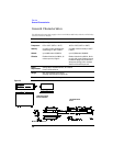
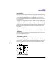
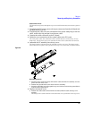
Attenuator Adapters
The 10x and 100x Attenuator Adapter are similar. A ceramic substrate carries two
attenuators, one for each input polarity. A variable resistor adjusts the low-frequency
balance (LF CMRR) between the two attenuators. The high-frequency adjustments are
the same for each attenuator. Each attenuator is adjusted differently. One attenuator is
adjusted for optimum pulse response and the other for best high-frequency CMRR.
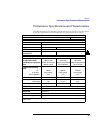
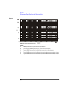
Figure 3-5
Attenuator Adapter, Simplified Schematic