


67
Service
Removing and Replacing Assemblies
Reassemble Probe
The ground screw passes through the top cover and PC board and screws into the ground
block.
1
If replacing the PC board, remove the input connectors from the old board and
put them on the new one.
2 If replacing the cable, note the orientation of the probe clamp ring on the old
cable, remove the ring and put it on the new cable.
3 Connect the cable connector to the PC board.
4 Solder the two connections of the coaxial cable to the PC board.
On a new probe cable, the conductors of the coaxial cable are connected by a heavy
single wire. Cut the heavy wire so it matches the wire on the cable that was removed.
5 Assemble the PC assembly into the top cover.
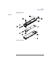
The large hybrid is exposed when the assembly is in the top cover. The figure on the
below shows the sequence of the ground screw, top cover, PC board, and ground block.
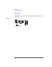
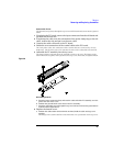
Figure 3-8
Reassembling the Probe
a
Insert the input connectors first, and seat the cable end of the PC assembly over the
pins at the rear of the cover.
b Position the ground block at the front of the PC assembly.
c Insert the grounding screw through the top cover and screw it into the ground block
as shown in the figure above.
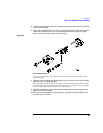
6 Replace the bottom cover.
a Position the cable strain relief and with one hand, hold the cable and top cover
together.
The flange on the strain relief has a notch that fits over a protrusion in the top cover.