


31
Calibration Tests and Adjustment
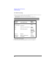
dc Gain Accuracy
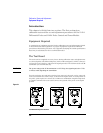
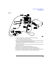
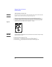
Figure 2-4
Signal to + input
3 Set the dc calibrator output 3 V dc.
4 Record the V
in1
measurement from the top DVM in figure 2-2.
5 Record the V
out1
measurement from the bottom DVM in figure 2-2
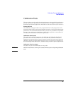
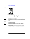
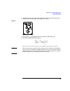
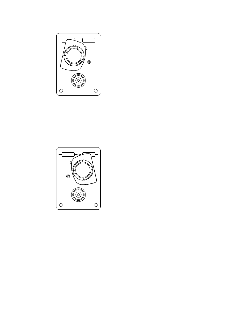
6 Carefully connect the input of the probe/attenuator to the test board in the
position shown in the figure below (signal to - input).
Figure 2-5
Signal to - input
7 Record the V
out2
measurement from the bottom DVM in figure 2-2.
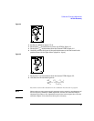
8 Calculate the 10x attenuator gain as
Record the result of this calculation in the “Calibration Test Record” on page 39.
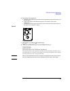
NOTE Failure of the accuracy test for the 10x attenuator can be caused by mis-adjustment of
the low-frequency CMRR (LF CMRR) adjustment. Perform the Attenuator Adapter
Adjustment procedure in the Adjustments section later in this chapter then retest the
attenuator adapter. If if continues to fail, repair is necessary.
∆V
out
∆V
in
--------------
V
out
1
V
out
2
–()
2 V
in
1
×
----------------------------------=