


50
Calibration Tests and Adjustment
Attenuator Adapter Adjustment
Adjustment Procedure
NOTE The attenuator must be adjusted when installed on the 1141A probe with which it will
be used. The specifications and characteristics will not be met if the attenuator adapter
is adjusted with one differential probe then used with another.
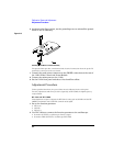
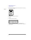
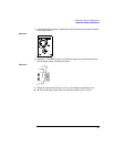
1 Remove the probe pins from the attenuator adapter and differential probe, then
attach the adapter to the probe.
2 Set the 1142A front panel switches to Local and Zero offset.
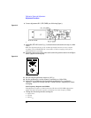
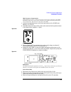
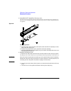
3 Use the 9-inch BNC cable to connect the function generator to the test board.
The short cable minimized ground-loop voltages.
4 Set up the function generator.
• Square wave
• 3.5 kHz
• 3.0 Vp-p for 10x adapter and 16 V
p-p
for a 100x adapter.
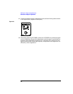
5
Use the long BNC cable to connect the Trig Out of the function generator to
the EXT TRIG of the oscilloscope.
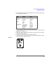
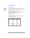
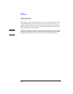
6 Set up the oscilloscope, then set the following parameters.
Menu Selection Setting
TIMEBASE (time/div) 50 µs/div
CHAN 1 (sensitivity)
(input R)
50 mV/div
50 Ω DC
TRIG (mode)
source
level
trg’d
EXT
1.00000 V
ACQUISITION Sampling Mode
Memory Depth
Sample Rate
Averaging
# of avg
Real Time
Automatic
Automatic
Enabled
32