


13
Operating the Probe
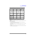
Recommended Test Equipment
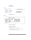
5 Set up the 1142A:
a Set the Local/Remote push button to Local.
b Under DC Couple, press Zero offset.
6 Set the power supply output to 5 V.
7 Arrange a connection between the power supply and the test board. The
negative terminal of the supply should connect to the shield of the test board
BNC.
If your power supply has standard binding posts, you can connect a banana-to-BNC
adapter to the supply and connect a BNC cable between the supply and the test board.
Adjustment
Warm up the 1141A for 30 minutes before making adjustments.
1
With the 1141A probe inputs unconnected, adjust Offset Null on the 1142A for
a minimum reading on the DVM.
The voltage swing of the adjustment is approximately ±4 mV.
2
On the 1142A, under DC Reject, press 5.0 Hz.
3 Read and record the reading on the DVM, _________ mV.
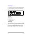
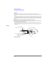
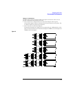
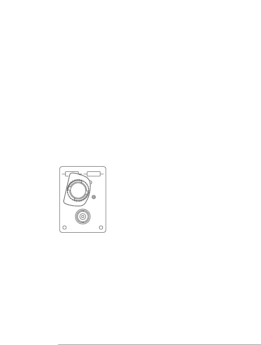
4 Connect the probe to the test board in the position shown below
(signal to + input).
Figure 1-6
Signal to + input
5 After the DVM reading stabilizes, adjust DC Reject Gain to the reading recorded
in step 3.
With a 5 V supply, the voltage swing is approximately ±12.5 mV. With a lower supply, the
voltage swings proportionally less.
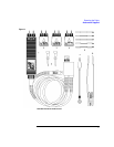
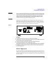
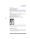
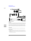
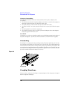
Using the Accessories
The 1141A Differential Probe and accessories are designed to provide a variety of ways
to connect to circuitry and make measurements. In the descriptions, any method used
to connect to the probe signal inputs also applied to the adapters. The figure below
shows, in a general way, the use of accessories.