


55
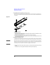
Service
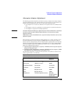
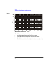
Performance Specifications and Characteristics
Performance Specifications and Characteristics
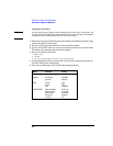
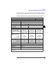
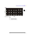
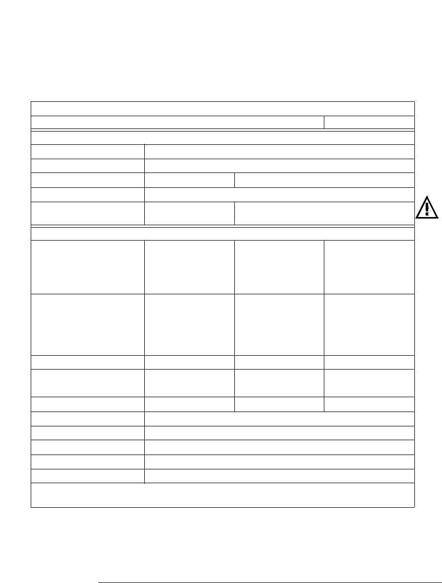
The following table gives performance specifications used to test the 1141A and 1142A.
It also gives performance characteristics that are typical for the probe system.
Performance Specifications and Characteristics
Parameter Probe alone With 10x attenuator With 100x attenuator
SPECIFICATIONS
Bandwidth (-3 dB, dc coupled) dc to 200 MHz
1
Rise Time: (calculated) 1.75 ns
Gain Accuracy 2.0% 4.0%
CMRR See the graphs in figure 3-1
Maximum Input Voltage
(see figure 3-2)
±200 V(dc + peak ac) ±500 V(dc + peak ac)
Differential Input Range
DC mode with no offset ± 300 mV peak ±3.0 V peak ±30 V peak
with DC Reject or appropriate
offset
±20 Vdc, decreasing to
±300 mV at 30 Hz
±200 Vdc, decreasing to
±3.0 mV at 30 Hz
±500 Vdc, decreasing to
±30 mV at 30 Hz
Common-mode Operating
Range
dc
dc to 30 Hz
30 Hz to 200 MHz
±20 Vdc
linear change
±0.5 V
±200 Vdc
linear change
±5 V
±500 Vdc
linear change
±50 V
dc Offset Range ±20 V ±200 V ±500 V
Input Impedance Resistance
Capacitance
1 MΩ
7 pF
9 MΩ
3.5 pF
10 MΩ
2 pF
ac Low-freq. Response (-3dB) 15 Hz 1.5 Hz 1.5 Hz
dc Reject Response 5 Hz, 0.5 Hz, or 0.05 Hz (selectable irrespective of attenuator)
Output Impedance 50 Ω
Thermal drift ≤ 50 µVdc/°C
Displayed noises ≤ 50 µV
rms
Overload Recovery < 1 ms from overdrive that is less than the common mode range
Note: 1. For maximum signal fidelity above 100 MHz, limit the probe input (without attenuators to ≤ 300 mV
peak-to-peak.