


34
Calibration Tests and Adjustment
Bandwidth
Bandwidth
This test checks the high-frequency response of the 1141A Differential Probe. The
bandwidth of the oscilloscope is characterized first so it is not a factor in the
measurement.
Specification (-3dB, dc coupled): dc to 200 MHz
Equipment Required
Procedure
This test depends on the accuracy of the termination on the test board and the
termination in the oscilloscope. Both should be with 1%.
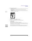
1
With the N cable and N-to-BNC adapter, connect the signal generator to the
oscilloscope channel 1 input.
2 Set the signal generator for 200 MHz at 0 dBm (about 224 mVrms).
3 Set the 1142A front panel switches to Local and Zero offset.
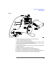
4 On the oscilloscope press AUTOSCALE, then set the following parameters.
5 The signal on screen should be about six divisions amplitude.
Measure the peak-to-peak voltage of the channel 1 signal and record the
reading.
V
p-p
(1) = _____________ mV
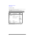
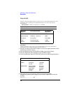
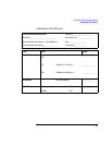
Equipment
Required
Critical Specifications Recommended
Model/Part
Oscilloscope 400 MHz bandwidth 54830A
Signal Generator 200 MHz at ≈ 230 mVrms 8648A
Test Board No substitute 01141-66504
Cable Type N (m) 24-inch 11500B
Adapter Type N (f) to BNC (m) 1250-0077
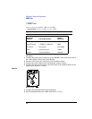
Menu Selection Setting
TIMEBASE (time/div) 2 ns/div
CHAN 1 (sensitivity)
(input R)
100 mV/div
50 Ω DC
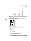
ACQUISITION Sampling Mode
Memory Depth
Sample Rate
Averaging
# of avg
Real Time
Automatic
Automatic
Enabled
32