


10
Operating the Probe
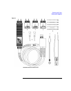
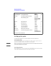
Recommended Test Equipment
Setting up the probe
The following paragraphs cover system preparation and initial adjustments.
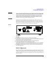
Power Requirements
The 1141A/1142A probe system (specifically the 1142A) requires a power source of
either 90 to 132/198 to 264 Vac, 47 to 440 Hz, 25 VA maximum.
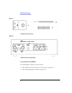
CAUTION Before connecting power to this instrument, be sure the line voltage switch on the rear
panel of the instrument is set properly.
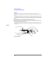
Line Voltage Selection
Before applying power, verify the setting of the LINE SELECT switch on the rear panel
of the 1142A. The slide switch can be set to either 115 or 230 V.
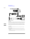
Test Board No substitute (supplied accessory) 01141-66504 A
Load BNC Feedthrough, 50 Ω Pasternack
Enterprises PE6008-
50 or Huber+Suhner
22543742
P
Cables (2) BNC, 50 Ω 36-inch 10503A P,A
Cable BNC, 50 Ω 9-inch 10502A A
Cable Type N (m) 24-inch 11500B P
Adapter Type N (m) to BNC (f) 1250-0780 A
Adapter Type N (f) to BNC (m) 1250-0077 P
Adapters (2) BNC (f) to dual banana (m) 1251-2277 P
Alignment tool Small flat blade (supplied accessory) 8710-1961/
Sprague-Goodman
part number GTT-5G
A
P=Calibration Tests, A=Adjustments
Equipment Required Critical Specifications
Recommended
Agilent
Model/Part Use