


41
Calibration Tests and Adjustment
Probe Adjustment
The following equipment is required for this procedure. Procedures are based on the
model or part number recommended.
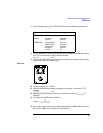
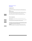
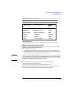
Equipment Required
Probe Preparation
The probe cover must be removed before adjustment. Drift due to temperature
differences with and without covers is negligible.
1
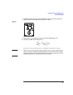
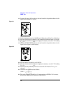
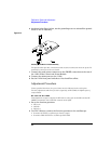
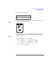
Remove the probe tip caps and probe tips.
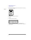
2 Loosen the probe clamp ring at the cable end of the probe (1/4 turn counter-
clockwise) and slide it down the cable.
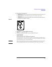
3 Remove the bottom cover.
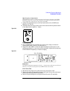
a At the cable end of the probe, separate the covers about centimeter (1/2 inch).
b Slide the bottom cover toward the cable end of the probe until the locator pins at
the probe input clear the holes. Then, remove the cover.
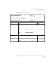
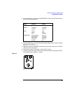
NOTE Note the position of the ground block at the input end of the probe. The ground block
is held, through the PC assembly, by the grounding screw on the top of the probe. The
ground block must be reinstalled on the PC assembly after the top cover is removed.
Handle the PC assembly by the edges of the PC board.
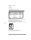
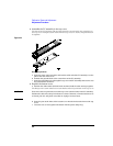
4 Remove the ground connection screw on the top of the probe.
The ground block will become free.
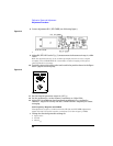
At the cable end, the PC board fits over pins inside the top cover.
5
Lift the board off of the pins in the cover and slide it in the direction of the
cable until the input connectors clear the front of the probe.
Equipment Required Critical Specifications Recommended
Agilent
Model/Part
Function Generator 2.5 kHz, 1 V
p-p
33120A
Oscilloscope 300 MHz at 1 mV/div 54830B
Signal Generator 200 MHz at ≈ 300 mVrms 8648A
Test Board No substitute 01141-66504
Cables (2) BNC, 50 Ω 10503A
Adapter Type N (m) to BNC (f) 1250-0780