67
9. Contrast methods for Leica DM4000 B/DM4500 P/DM5000 B
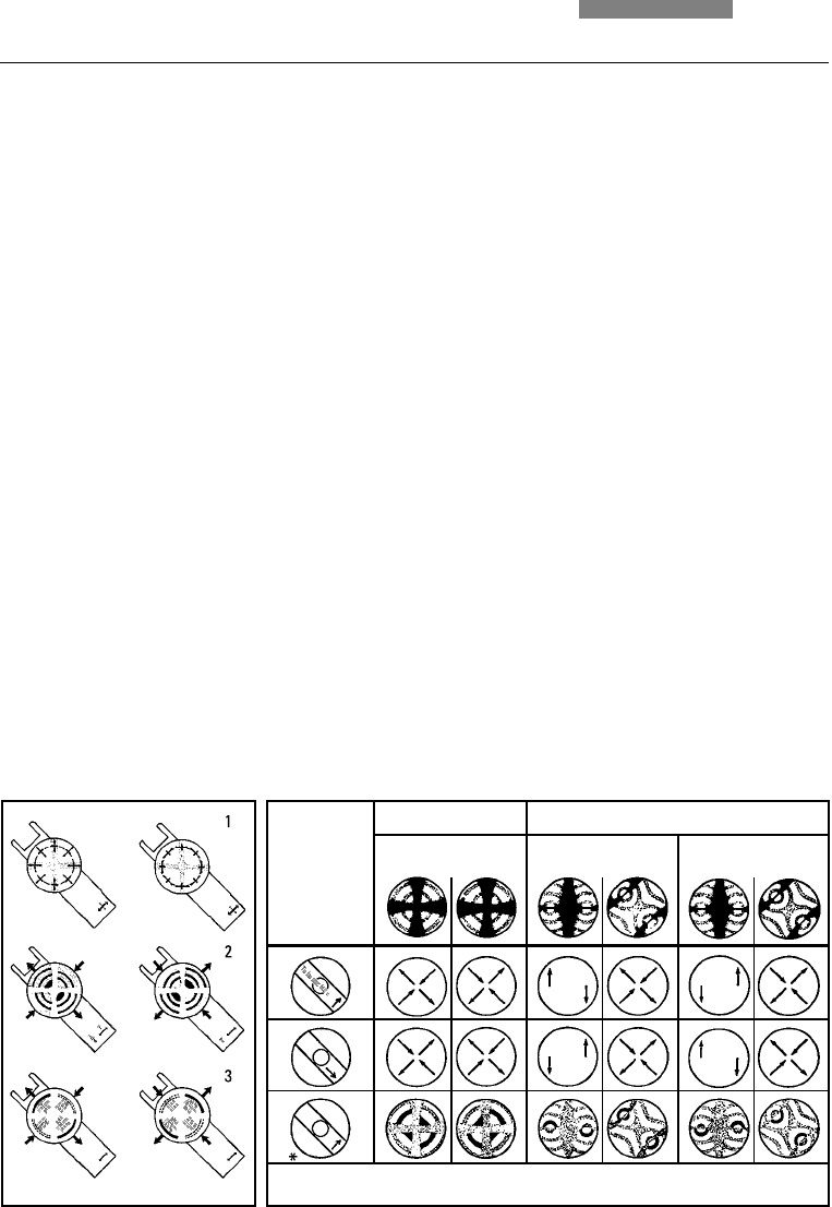
Fig. 71a Determining the optical characters for uniaxial structures
Left: Positive uniaxial crystal, cut perpendicular to the optical axis.
Right: Negative uniaxial crystal, cut perpendicular to the optical axis.
1 Illustration of the vibration directions in the specimen and in the compensator
2 Interference figure changes when using a λ/4 plate,
3 Interference figure changes when using a λ/plate,
Fig. 71b Table for determining the optical character
Biaxial, positive crystals:
When the compensator is activated, the move-
ment of the interference bands proceeds from
the convex side to the concave side of the
isogyres.
Biaxial, negative crystals:
The interference bands move from the concave
side to the convex side.
Possible faults
The polarizers have been damaged (discolored)
by strong light sources or they are heavily
soiled.
The objectives or the condenser have been de-
formed by mechanical damage.
There is a beam splitter or filter between the po-
larizers.
The embedding material for transmitted light
specimens is birefringent.
λ
λ
γ
λ
γ
γ
γ
γ
γ
+
–
+
–
+
+
–
–
* When using 1/4-λ glimmer plates, black points appear instead of black arcs.
Uniaxial Biaxial
Orientation
of the
condenser
plate


