


63
9. Contrast methods for Leica DM4000 B/DM4500 P/DM5000 B
Simple overview observations
• Place the transmitted light specimen on the
polarizer.
• Turn the condenser head inward.
• Focus through the condenser using a low-
power magnifying lens, such as a 5x.
Although this method does not provide good im-
aging performance; it does make it possible to
view rows of specimen very quickly.
λ/4- and λ plate, quartz wedge
Depending on their design, λ/4 and λ plates are
installed on the underside of the condenser or,
for polarizing microscope, in the 8x condenser
disk (the vibration direction γ runs: ) or they
are inserted in the tube slot. An automatic,
spring-mounted dust cover flap closes the tube
slot.
For the IC/P analyzer, the λ plate can be activat-
ed by turning it so that the mark "I" is facing up-
wards.
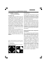
When the plate is activated, the path difference
is increased or reduced according to Fig. 68.
The corresponding color changes can be used
to determine the vibration direction γ according
to the larger refractive index (i.e. refractive
index n
γ
). (The quartz wedge (69.7) allows
various color shifts on the polarizing
microscope.)
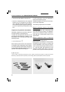
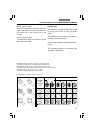
Fig. 68 Interference color with dependence on the path
difference or on the thickness and color changes in the addi-
tion and subtraction areas of the λ and λ/4 plates.
schwarz
lavendelgrau
graublau
gelblichweiß
lebhaftgelb
rotorange
tiefrot
indigo
himmelblau
grünlichblau
hellgrün
reingelb
orangerot
dunkelviolettrot
indigo
grünlichblau
meergrün
grünlichgelb
fleischfarben
kaminrot
mattpurpur
– λ
+ λ
200
400
600
800
1000
1200
1400
1600
Gangunterschied
1. Ordnung
2. Ordnung
3. Ordnung
λ
– –
4
λ
+ –
4
Circular polarization
When the specimen stage is rotated, birefrin-
gent specimens show 4 extinction positions.
When a larger number of birefringent speci-
mens are present, a few birefringent specimens
always show up randomly in the extinction posi-
tion. Circular polarization is used for simulta-
neous interference color observation of all
specimens:
• Remove the specimen from the beam path or
locate the blank position of the specimen.
• Cross the polarizers precisely. The polarizers
must be positioned exactly in the N – S/E – W
direction. This means that the analyzer must
either be set exactly at 90° or 0° of polariza-
tion.
∩