


65
9. Contrast methods for Leica DM4000 B/DM4500 P/DM5000 B
ence; rather, it provides only the difference over
the entire wavelength or over a multiple of the
wavelength. Entire wavelengths must be
defined using a tilt compensator, a quartz wedge
and by measuring the interference color. The
results are more accurate than those obtained
using a tilt compensator only.
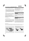
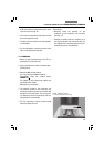
Tilt compensator B with a measurement range
of up to 5 orders based on Berek techniques
Compensator (69.8) with an MgF
2
plate for mea-
suring up to approx. 5 orders of path differences
in white or monochromatic light. You can read
the path difference directly from the provided
measurement table by calculating the sum of
the two angles that are formed when the com-
pensators are tilted simultaneously.
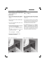
Tilt compensator K with a measurement range of
up to 30 Orders (69.7)
For measuring path differences in white or
monochromatic light up to the specified maxi-
mum path difference. The compensator plate is
made of calcite. The evaluation is created by
performing simple calculations using the provid-
ed tables and the specified measured
constants. Measure in white or monochromatic
light.
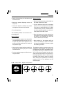
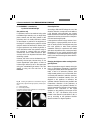
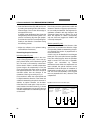
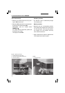
Using conoscopy for crystal structures
Birefringent crystals create interference imag-
es, also called axis images or conoscopic imag-
es (Fig. 71a,b), in the exit pupil of the objective
(e.g. inside the objective). The form of these in-
terference images and the changes that occur
in these images when using a compensator
make it possible to state how many axes the
crystals have (uniaxial or biaxial crystals), how
the axes are oriented, and whether or not the bi-
refringence is positive or negative (positive or
negative birefringent crystals).
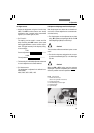
Because the interference images appear in the
eyepoint, they are not visible during typical
observation (orthoscopy). An improvisational
method for observing these images is to remove
the eyepiece from the tube and to use a monoc-
ular, held a few cm away, for looking into the
tube. You can improve the observation by using
a focusing telescope for the phase contrast.
However, additional crystals located in the
field of view need to be masked out because
they disrupt the interference images of a
crystal located in the middle of the field of
view.
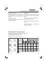
Setting the conoscopy
For conoscopy, the specimen positions that are
most suitable are those that have the lowest
path differences (table Fig. 68).
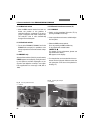
Efficient conoscopic observation requires that
the objective be centered precisely and that the
cross position of the polarizers is exact.
• Rotate an objective with an aperture that is as
high as possible (e.g. 40x, 50x or 63x) into the
beam path.
• Rotate the condenser head into the beam
path.
• Open the aperture diaphragm.
• Place the crystal being examined as close to
the center of the field of vision as possible.
• Turn the 1.6x tube lens inward.
• Widen or narrow the iris diaphragm according
to the size of crystal, and make the field dia-
phragm narrower if necessary.