


66
9. Contrast methods for Leica DM4000 B/DM4500 P/DM5000 B
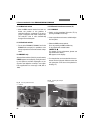
• Insert the Bertrand lens (Fig. 70B) and focus it
by rotating the operating button until the inter-
ference image or the circular diffuse edge of
the eyepoint is in focus.
If needed, center the Bertrand lens: Insert the
hexagonal keys into the centering holes in se-
quence. If necessary, align the right eyepiec-
es so that the cross-hairs correspond approx-
imately to the direction of movement during
the centering process.
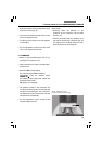
• Adjust the collector to its optimum setting;
use the diffuser if necessary.
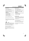
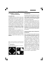
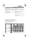
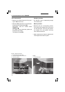
Determining the optical character
Uniaxial crystals (Fig. 71a)
When observing uniaxial crystals in the cono-
scopic (diverging) beam path, a dark cross ap-
pears whose center point indicates the optical
axis. The cross is surrounded by colored inter-
ference bands*. When a variable compensator
(quartz wedge or tilt compensator) is used, the
rings move toward the center point or outside
two opposite quadrants in the cross. The optical
character results from the direction of the
movement of the rings according to Fig. 71.
Cross sections in which the crystal optical axis
is sloped toward the direction of the viewer are
suitable for determining the optical character. In
addition, an optical character can be deter-
mined even if the center point of the cross is lo-
cated outside of the field of view. Fig. 71 shows
that fixed compensators can be used in place of
variable compensators for determining the opti-
cal character.
Even if only one of the optical axes is within the
observer’s direction of sight, the optical charac-
ter can usually be identified. The brightness for
specimens oriented in this way changes in the
orthoscopic beam path very little or not at all
when the objective is rotated. Consequently,
only one of the two isogyres are visible in the
conoscopic beam path.
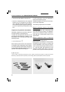
Biaxial crystals (Fig. 71b)
The cross sections in which the bisectors of the
optical axes run parallel to the direction of sight
are especially suitable for determining the opti-
cal character (the section is perpendicular to
the acute bisectrix).
A dark cross can be identified in the divergent
beam path. This cross splits into two hyperbolic
lines, also called isogyres, when the specimen
stage is turned. The cross and or hyperbolic
isogyres are surrounded by colored
interference bands. After the compensator has
been activated, the optical character can be
determined from the direction of movement of
these bands according to Fig. 71 or the following
rule: The screw axis symmetry of the isogyres
must run perpendicular to the γ−direction of the
compensator:
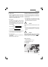
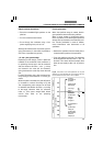
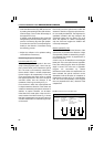
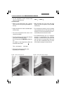
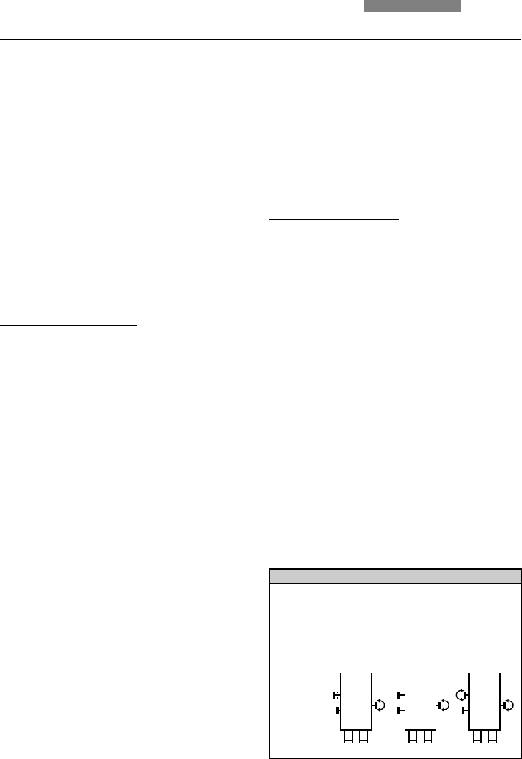
Fig. 70 Functions of the HC P Pol tube optics
Control element 1x Orthoscopy 1.6x Orthoscopy Conoscopy
Tube lens 1x 1.6x 1.6x
Iris diaphragm user-defined, adapted for > Specimen
as it is not the field of vision
Bertrand lens in the beam path off on
Polarization on or off on or off crossed
(not for Dichroism/
Pleochroism)
O/B
1x
I
O
1.6x
I
B
1.6x
I