


Instruction Manual
IM-106-880, Rev 1.0
January 2007
6-27
OCX 8800
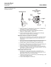
Install O
2
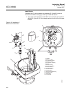
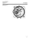
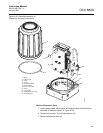
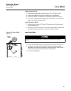
Cell and Heater Strut Assembly
1. Rub a small amount of anti-seize compound on both sides of new
gasket (10, Figure 6-20).
2. Apply anti-seize compound to threads of O
2
cell and heater strut
assembly (9) and sensor housing (8).
3. Install O
2
cell and heater strut assembly (9) in sensor housing (8). Snug
up, but do not over-tighten the assembly.
4. Reconnect the lead wires from O
2
cell, heater, and thermocouple to the
sensor housing terminal blocks. Refer to Figure 6-21.
5. Install reference air tube (7, Figure 6-20) in sensor housing (8). Make
sure that the open end of reference air tube extends into heater tube of
O
2
cell and heater strut assembly (9).
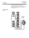
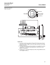
Install Terminals Insulator and Cover
1. Install insulator (6, Figure 6-20) over uppermost terminal blocks.
Position one side of insulator against terminal blocks and snap terminal
marking plate (5) to mating stand-off.
2. Position opposite side of insulator (6) and secure with related marking
plate (5).
3. If removed, install cover gasket (4). Screw cover (3) onto sensor
housing (8). Tighten cover firmly.
4. To comply with explosion-proof requirements, the cover gasket (4) must
be compressed. For hazardous area applications, verify that the cover
gasket is compressed.
5. Align locking clip (2) with gap between cover ribs.
6. Loosen screw (1) and slide locking clip (2) fully into gap between cover
ribs. Retighten screw (1).
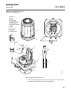
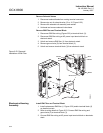
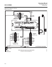
Sensor Housing Leak Test
1. Install 1/4 NPT cap on dilution air inlet fitting. Install a 1/4 NPT cap on
sample tube (2, Figure 6-11) or plug 1/4 NPT sample inlet port. Capped
or plugged ports must be air tight.
2. If not in place, install exhaust tube (3, Figure 6-11) in exhaust port
according to the instructions provided.
3. Connect a calibrated manometer to the CAL GAS inlet port.
4. Connect and apply clean instrument air at 35 psig (241 kPa gage) to the
instrument air inlet fitting.
5. Observe the manometer reading. The reading should be from 10 to 13
inches, Water Column. Locate and correct leaks if the reading is less
than 10 inches WC.
Stripped threads on the O
2
cell and heater strut assembly can allow gas leakage. Gas
leakage can affect the O
2
measurements and calibration. Avoid over-tightening the O
2
cell
and heater strut assembly .