


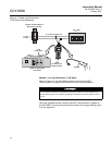
Instruction Manual
IM-106-880, Rev 1.0
January 2007
OCX 8800
3-2
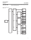
Verify Configuration
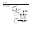
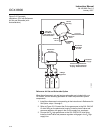
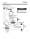
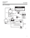
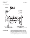
There are three switches on the microprocessor board which are user
configurable for the OCX 8800 (Figure 3-1). SW1 determines if the O
2
4-20
mA signal is internally or externally powered. SW2 determines if the COe 4-20
mA signal is internally or externally powered. SW3 sets the rail limits for the
O
2
and COe 4-20 mA signals and configures the sample line heater control
circuit. All switches are accessible through holes in the electronics box.
Verify that the following switch settings are correct for your OCX 8800
installation:
SW1 The two settings are internally or externally powering the O
2
4-20
mA signal. The factory setting is for the O
2
4-20 mA signal to be internally
powered.
SW2 The two settings are internally or externally powering the COe 4-20
mA signal. The factory setting is for the COe 4-20 mA signal to be
internally powered.
SW3 The factory sets this switch as follows:
• Position 1 determines the O
2
4-20 mA signal rail limit. The settings are
high, 21.1 mA, or low, 3.5 mA. The factory setting is low, 3.5 mA.
• Position 2 determines the COe 4-20 mA signal rail limit. The settings
are high, 21.1 mA, or low, 3.5 mA. The factory setting is high, 21.1 mA.
• Positions 3 and 4 must be set as shown for proper software control of
the device heaters.
Remove power from the OCX 8800 before changing defaults. If defaults are changed under
power, damage to the electronics may occur.