


Instruction Manual
IM-106-880, Rev 1.0
January 2007
1-7
OCX 8800
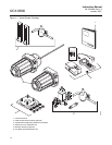
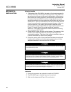
After verifying that you have all the components, select mounting locations
and determine how each component will be placed in terms of available line
voltage, ambient temperatures, environmental considerations, convenience,
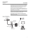
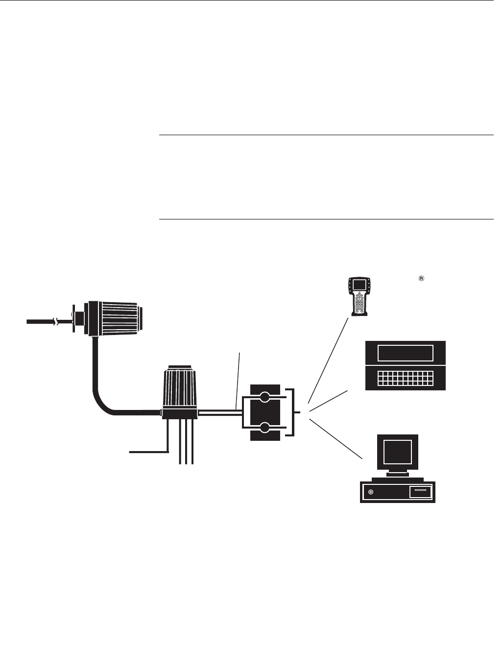
and serviceability. Figure 1-3 shows a typical system wiring. Simplified
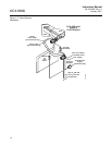
installations for the OCX 8800 are shown in Figure 1-4.
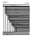
A source of instrument air is required at the OCX 8800 for reference air,
dilution air, and eductor air. Since the OCX 8800 is equipped with an in-place
calibration feature, provision should be made for connecting test gas tanks to
the OCX 8800 when it is to be calibrated.
NOTE
The electronics module is designed to meet NEMA 4 (IP66) and the electronic
components are rated to temperatures up to 185°F (85°C).
Retain packaging in which the unit arrived from the factory in case any
components are to be shipped to another site. This packaging has been
designed to protect the product.
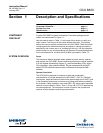
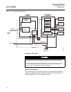
Figure 1-3. OCX 8800 HART
Connections and AMS Application
37390065
4-20 mA Output
(Twisted Pairs)
Instrument
Air
3 calibration
gas lines by
customer
[300 ft (91 m) max.)
OCX 8800
Sensor Housing
HART
Model 275/375
Handheld
Communicator
Customer’s Laptop
with AMS
Termination in
Control Room
AMS
OCX 8800
Electronics Housing