


Instruction Manual
IM-106-880, Rev 1.0
January 2007
6-11
OCX 8800
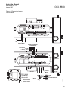
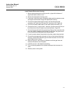
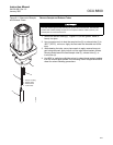
2. Loosen screws (11, Figure 6-5) and rotate heater clamps (12) to release
heater rods (13). One heater clamp secures each heater rod.
3. Slide sample block heater rods (13) out of housing (8).
4. To replace thermal switch (15), remove insulator (14). Disconnect
heater wires. Unscrew and remove thermal switch.
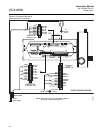
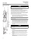
Remove COe Sensor Assembly
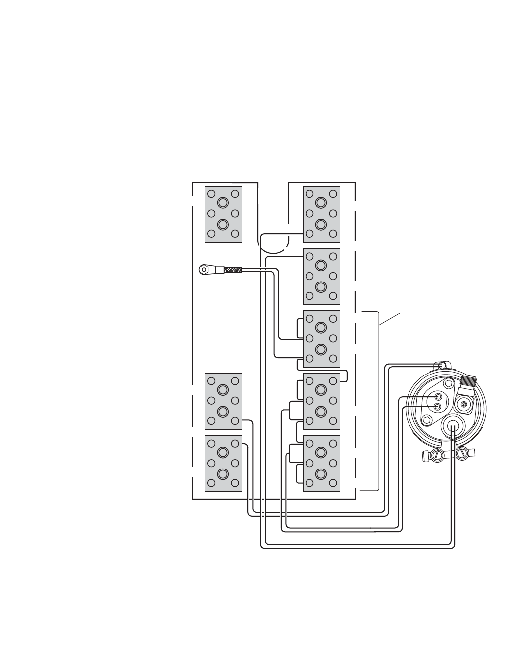
1. Disconnect COe heater, thermocouple, and sensor wires from terminal
blocks. Refer to Figure 6-7.
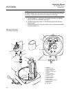
2. Remove insulator (1, Figure 6-8).
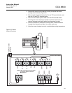
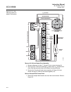
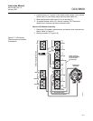
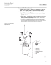
Figure 6-7. COe Sensor,
Thermocouple, and Heater
Connections
O2
RED
T/C O2
T/C CO
T/C SB
EXC
CJC
COe SensorWires
COe HeaterWires
COe Sensor
Assembly
CO REF
CO ACT
Sensor HousingTerminals
+
-
HTR 02
HTR SB
2
2
1
+
-
+
-
+
-
+
-
+
-
+
YEL
-
+
37390018
HTR 02
2
1
HTR CO
1
WHT
BLU
RED
RED
WHT
COeThermocoupleWires
-
EXC
RED
BLU
CJC Sensor
NOTE: All wires
at these terminals
are in the CJC
current loop.