


Instruction Manual
IM-106-880, Rev 1.0
January 2007
OCX 8800
7-2
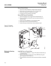
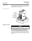
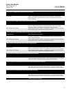
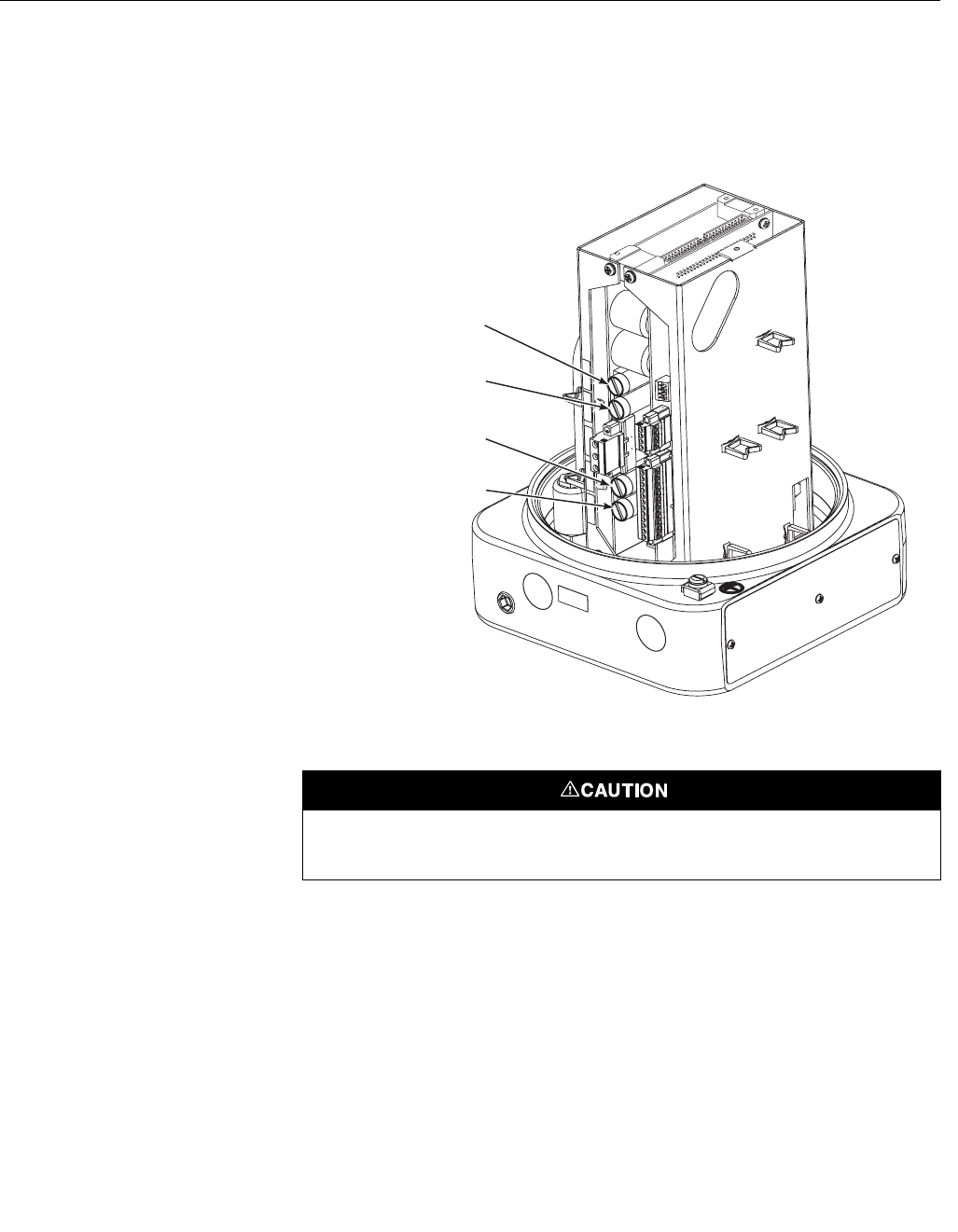
Total Power Loss In the event that the OCX 8800 will not power up at all, check the incoming
power supply to make sure power is being delivered to the OCX 8800. If the
incoming power supply is good, then check fuses F1 and F6 in the electronics
housing. Refer to Figure 7-1 for fuse locations.
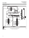
Figure 7-1. Fuse Locations
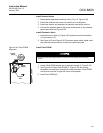
DIAGNOSTIC ALARMS
The OCX 8800 is equipped with a set of alarm relay contacts on the
microprocessor board in the electronics housing. This set of dry contacts can
be connected to any customer supplied relay device, 30 VDC, 30 mA
maximum. A blocking diode is required on the customers relay coil.
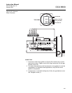
Any fault condition in the OCX 8800 will trip the alarm relay. The optional SPA
with HART programmable alarm indicates LOW O2, HIGH COe, Calibration
Status, and Unit Failure. For more information refer to Appendix B - SPA with
HART Alarm.
F6
Neutral (N)
10 Amp, 250VAC
F1
Line (L1)
10 Amp, 250VAC
F3
O2 and COe Heater
4 Amp, 250VAC
F4
Sample Block Heater
8 Amp, 250VAC
37390079
Always install a blocking diode on the customers relay coil. Failure to install a blocking diode
may create noise spikes and cause faults in the OCX electronics.