


Instruction Manual
IM-106-880, Rev 1.0
January 2007
OCX 8800
2-14
PNEUMATIC
INSTALLATION
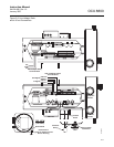
Pneumatic system connections depend on whether reference air set,
calibration solenoids, and/or blowback equipment options are equipped on
your transmitter. Refer to the following paragraphs and select the option that
applies to your transmitter configuration.
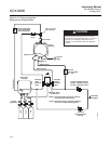
Reference Air Set Option (only)
When no options or only the reference air set option is equipped, use the
following procedure to install the pneumatic system components.
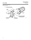
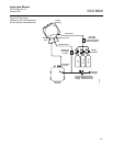
1. Refer to Figure 2-8. Connect the reference air set (regulator/filter and
pressure gage) to the instrument air inlet on the electronics housing and
to the inlet side of the dilution air flow meter.
2. Connect the dilution air flow meter output to the dilution air inlet fitting on
the sensor housing.
3. Install an air line between the instrument air outlet fitting on the
electronics housing and the tee fitting on the sensor housing.
.
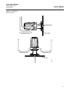
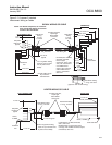
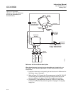
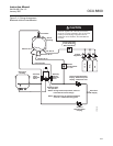
4. One CO gas and two O
2
gases are used to calibrate the OCX 8800:
CO - 1000 ppm or 4%
O
2
low gas - 0.4%
O
2
high gas - 8%
Connect the output of the test gas sources to the inlet port of the CAL
GAS flow meter. Install an air line between the flow meter outlet port and
the CAL GAS inlet fitting on the sensor housing.
Do not use 100% nitrogen as an O
2
low gas. It is suggested that O
2
low gas be between
0.4% and 2.0% O
2
. Do not use gases with hydrocarbon concentrations of more than 40
parts per million. Failure to use proper gases will result in erroneous readings.