


Instruction Manual
IM-106-880, Rev 1.0
January 2007
OCX 8800
6-24
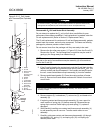
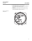
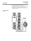
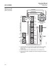
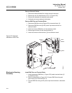
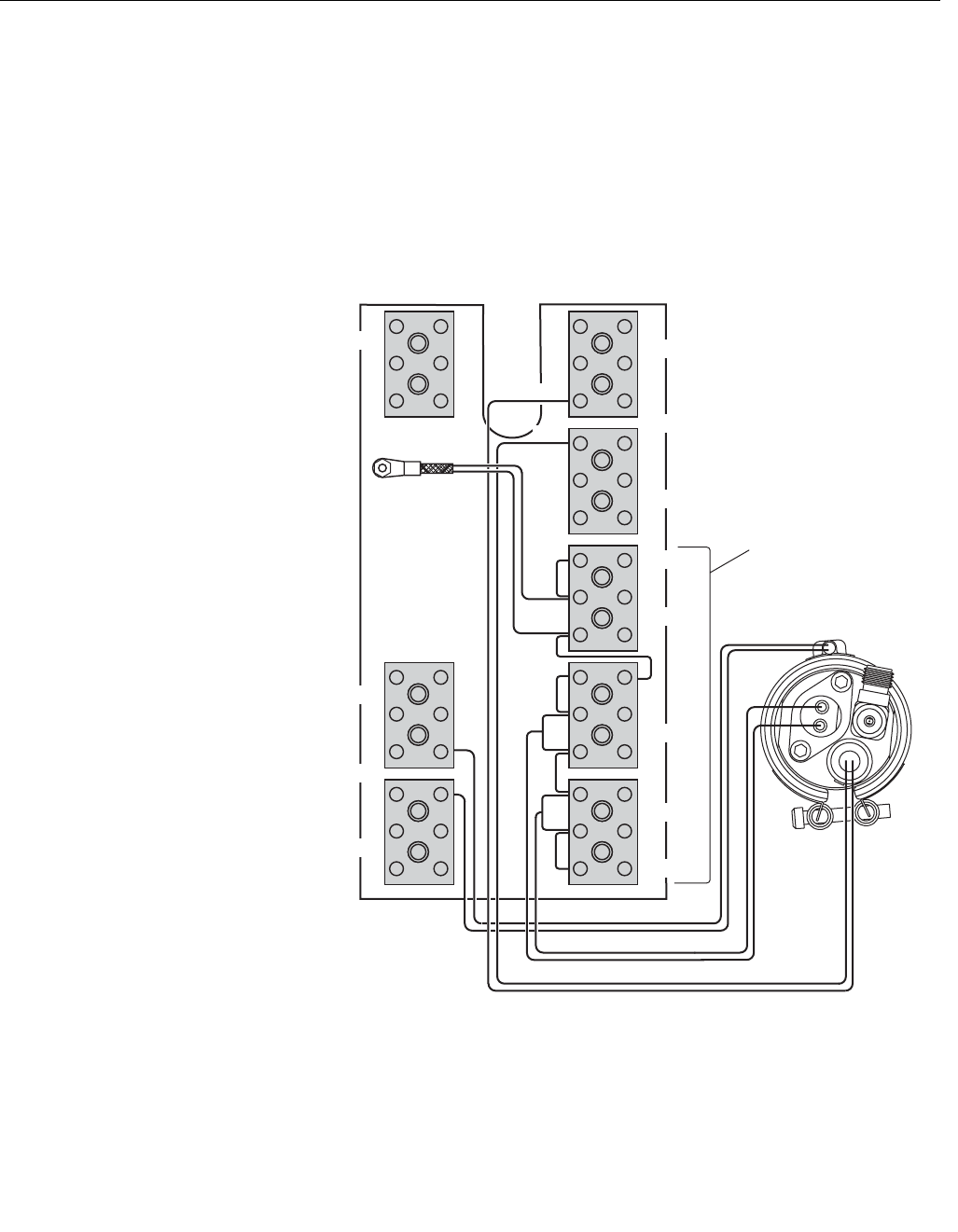
10. Reconnect the COe sensor, thermocouple, and heater wires at the
sensor housing terminal blocks. Refer to Figure 6-19.
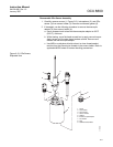
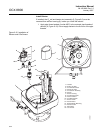
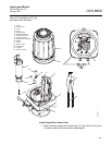
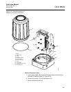
11. Install and fasten the COe insulator (1, Figure 6-15) around COe sensor
assembly (5). All wiring must remain outside of the insulator.
12. If terminal block mounting (13, Figure 6-15) was moved, reinstall with
two base mounting screws.
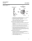
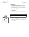
Figure 6-19. COe Sensor,
Thermocouple, and Heater
Connections
O2
RED
T/C O2
T/C CO
T/C SB
EXC
CJC
COe SensorWires
COe HeaterWires
COe Sensor
Assembly
CO REF
CO ACT
Sensor HousingTerminals
+
-
HTR 02
HTR SB
2
2
1
+
-
+
-
+
-
+
-
+
-
+
YEL
-
+
37390018
HTR 02
2
1
HTR CO
1
WHT
BLU
RED
RED
WHT
COeThermocoupleWires
-
EXC
RED
BLU
CJC Sensor
NOTE: All wires
at these terminals
are in the CJC
current loop.