Instruction Manual
IM-106-880, Rev 1.0
January 2007
2-13
OCX 8800
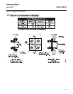
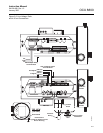
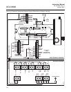
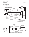
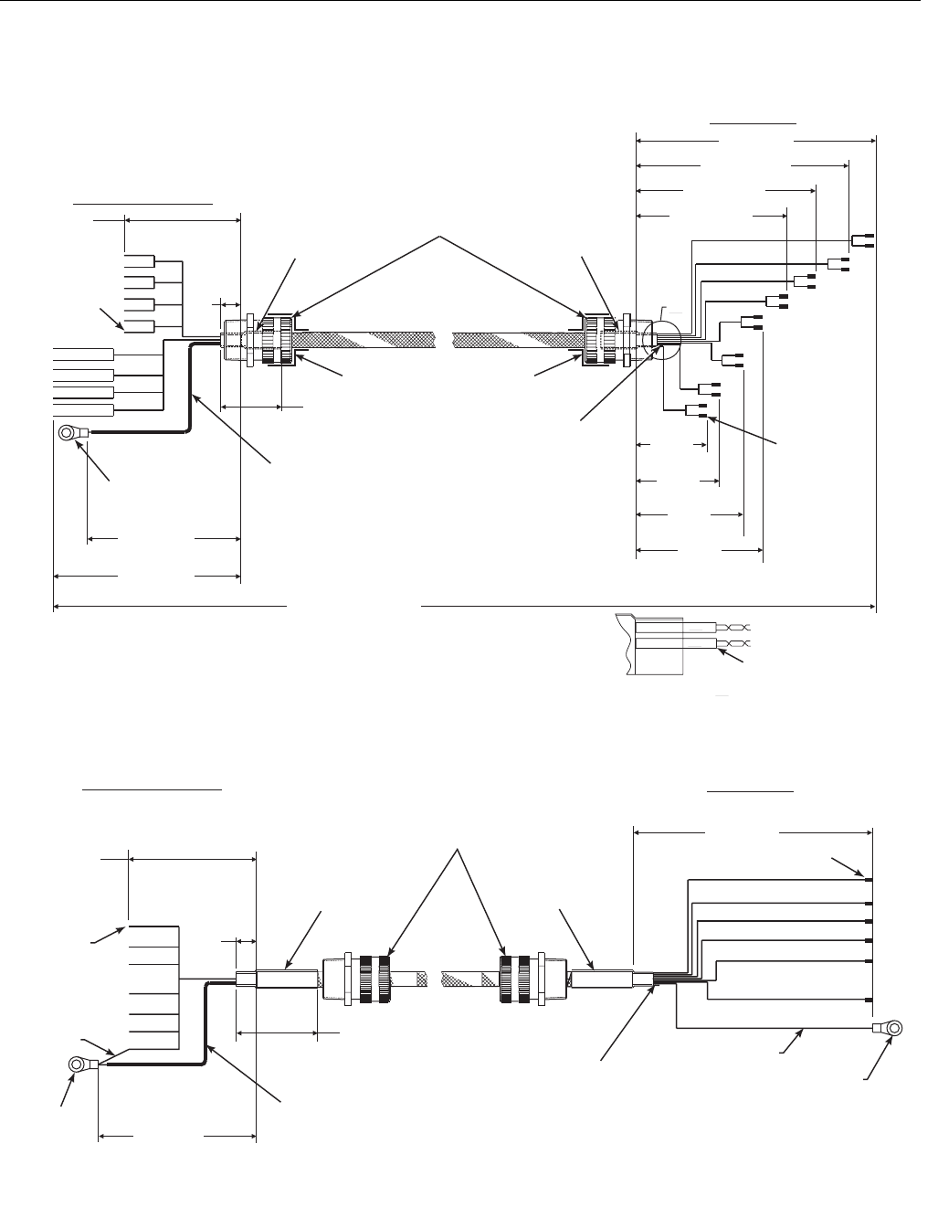
Figure 2-7. Customer-Furnished
Interconnect Wiring or Cables
A
#2
#1
3/4 NPT Hub Size,
Liquid-tight
Strain Relief
Connector
Heat Shrink
Tubing
2” Long
1/2” Size
7.0” Long Teflon Tubing,
0.042” ID (Cut off drain
wire at probe end of
shield).
8 twisted pairs 24 AWG,
stranded, insulated,
tinned copper
conductors, 200 C, 300
volts, with overall braid
of 34 AWG tinned
copper, 90% coverage
and 24 AWG tinned
copper, uninsulated
drain wire.
o
7.25
±0.10
Strip Wire
Ends 3/16”
Typical
7.25 ±0.10
9.25 ±0.10
Overall Cable Length
By Customer
150’ Maximum
3.875
±0.10
4.625
±0.10
5.375
±0.10
6.125
±0.10
6.875 ±0.10
8.625 ±0.10
10.375 ±0.10
12.5 ±0.10
Ferrule,
Uninsulated
2.0 ±0.25
Typical
DETAIL
A
Heat Shrink Tubing
1” Long, 3/16” Size
(typical on both ends of wiring)
SIGNAL WIRING OR CABLE
ELECTRONICS END
PROBE END
0.5
Typ.
3/4 NPT Hub Size,
Liquid-tight
Strain Relief
Connectors
Heat Shrink Tubing
2” Long, 1/2” Size
4.25” Long Teflon Tubing,
0.042” ID.(Cut off drain wire
at probe end of shield).
8 Conductors, 16 AWG, Stranded,
200 C, 600 volts.
Braided shield - tinned copper, 90%
coverage with 18 AWG 24 tinned copper,
uninsulated, drain wire.
O
4.0 ±0.10
Stud Size
#10
4.5 ±0.10
5.5 ±0.10
Ferrule, Uninsulated
2.0 ±0.25 Typical
Heat Shrink Tubing
2” Long, 1/2” Size
HEATER WIRING OR CABLE
ELECTRONICS END
PROBE END
Green,
16 AWG
0.5
Typ.
Stud Size #6
Green, 16 AWG
Strip Wire
Ends 3/16”
Typical
Heat Shrink
Tubing
2” Long
1/2” Size
See Note
See Note
NOTE: For RFI/CE compliance, the connector
must provide 360 degrees of electrical
contact to the cable shield.
Stud Size
#10
37390061


