


Instruction Manual
IM-106-880, Rev 1.0
January 2007
2-17
OCX 8800
4. Connect the CO high gas to the CAL GAS HI COe inlet fitting. Install a
shutoff valve and pressure regulator with gage in the CO high supply
line.
5. Connect the CAL GAS outlet fitting of the electronics housing to the inlet
port of the CAL GAS flow meter. Install an air line between the flow
meter outlet port and the CAL GAS inlet fitting on the sensor housing.
Reference Air Set, Solenoids, and Blowback Option
The blowback system blows instrument air back through the blowback filter
and out the sample tube of the transmitter. This removes built up dirt and
particulate from the filter and sample line. The blowback option is normally
used in systems that have a dirty process stream.
Installing an OCX 8800 with the blowback option requires the addition of air
operated blowback valve, regulator and gage, and check valve.
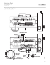
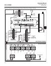
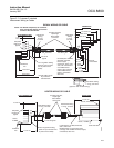
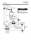
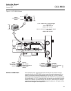
Figure 2-10 shows the piping arrangement for the OCX 8800 with the
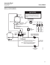
blowback and autocalibration options. Figure 2-11 shows the piping
arrangement for the OCX 8800 with the blowback option, but without
autocalibration (without test gas solenoids).
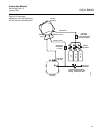
When the reference air set, calibration gas solenoids, and blowback options
are included with your transmitter, use the following procedure to install the
pneumatic system components.
1. Connect the calibration gas sources according to the instructions in the
previous paragraph “Reference Air Set and Solenoids Option”, steps 2
through 5.
2. Connect a clean, dry, instrument-quality supply of air (20.95% O
2
) to the
35/45 psig and 55 psig pressure regulators. The inlet to the 35/45 psig
regulator accepts a 1/8" NPT fitting. The inlet to the 55 psig regulator
accepts a 1/4" NPT fitting.
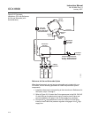
3. See the upper leg of the instrument air supply. Connect the output of the
35/45 psi regulator/filter to one port of the normally-closed air-operated
solenoid valve, and to the inlet side of the dilution air flow meter.
4. Connect the dilution air flow meter output to the DILUTION AIR inlet
fitting on the sensor housing.
5. Install an instrument air line between the open port of the normally-open
air-operated solenoid valve and the tee fitting on the sensor housing.
6. Connect the output of the 55 psi regulator/filter to one port of the
normally-open air-operated solenoid valve, and to the instrument air
inlet on the back of the electronics housing.
7. Install an air line between the open port of the normally-closed
air-operated solenoid valve and the check valve inlet fitting on the
sensor housing.