


Instruction Manual
IM-106-880, Rev 1.0
January 2007
OCX 8800
2-10
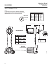
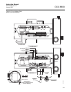
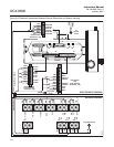
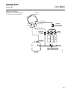
Remote Electronics Connections to Sensor Housing
Make the following connections between the electronics and sensor housings
with the electronics cable ordered with the package (Figure 2-6). Braided
cable is available in lengths up to 150 ft. (46 m).
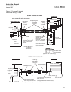
NOTE
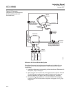
Interconnect wiring shown is for Rosemount Analytical supplied cables. For
customer furnished interconnect wiring or cables, refer to Figure 2-7.
Signal Connections
Connect the electronics housing terminals to the corresponding terminals
in the sensor housing. The twisted wire pairs are numbered on the inner
plastic wrapper. Keep twisted pairs together and match the numbers and
wire colors shown in Figure 2-6.
Heater Power Connections
Use the blue, white, orange black, red, and yellow stranded wires in the
heater power cable to connect power to the three heaters in the sensor
housing. Match the wire colors to the corresponding heater power terminal
blocks in the sensor and electronics housings as shown in Figure 2-6.