


Instruction Manual
IM-106-880, Rev 1.0
January 2007
OCX 8800
2-4
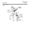
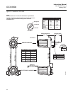
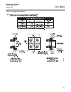
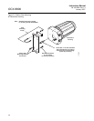
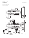
Figure 2-1. Installation, OCX 8800
B.C. Dia.
Removal Envelope
Dim “B”
37390009
Insertion Depth
Dim “A”
Flange Dia.
Hole Dia.
8.3
(211)
Allow 9 in.
(229 mm) for
Cover Removal
SeeTable 1
Optional
In Situ FIilter
Heater Power Cable
Signal Cable
Heater Power Cable
Signal Cable
ELECTRONICS HOUSING
SENSOR HOUSING
SeeTable 2
All dimensions are in inches with millimeters in parentheses.
NOTE
Insulate if exposed to adverse weather or extreme temperature
changes, install a protective housing and/or insulation
around the unit.
Flange
Dia.
DIN
ANSI
5R10244H025R10244H01
6.00
(152)
Table 1. Mounting Flange
Hole
Dia.
(4) Holes
equally
spaced on
B.C. dia
7.28
(185)
0.75
(19)
0.71
(18)
4.75
(121)
5.71
(145)
Dim "B”
3 ft
9 ft
6 ft
Probe
18 in.
Dim "A”
(2235)
88
(3150)
124
(2743)
108
72
(1829)
(914)
36
(1321)
52
(864)
34
(457)
18
Table 2. Installation/Removal
3535B18H02
3535B45H01
DIN
ANSI
0.06 In. Thick Gasket