


Instruction Manual
IM-106-880, Rev 1.0
January 2007
OCX 8800
6-22
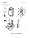
Install COe Sensor Assembly
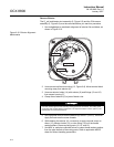
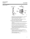
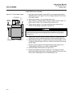
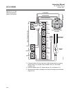
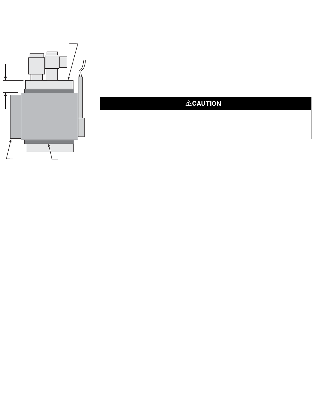
Figure 6-17. Band Heater Height 1. Apply pipe thread sealant (Loctite #567) to the exposed pipe threads
of eductor elbow (12, Figure 6-15). Do not apply sealant to the first turn
of the pipe threads.
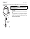
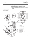
2. Screw sensor holder (11) onto eductor elbow (12).
3. With wrenches on eductor elbow (12) and on flats of sensor holder (11),
tighten sensor holder. Do not allow eductor elbow to turn.
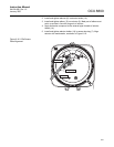
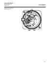
4. Tighten sensor holder (11) to align outside flat with matchmark on
sensor housing flange, as shown in Figure 6-18.
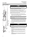
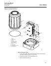
5. Wrap heater insulator (9) around sensor holder (11). Make sure the
insulator joint lines up with the band gap of the COe band heater (10).
6. Slide COe band heater (10, Figure 6-15) up onto sensor holder (11). Do
not tighten the band heater at this time. Heater must rotate freely around
sensor holder.
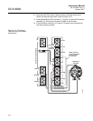
7. Check for proper height of COe heater thermocouple (Figure 6-14).
Thread bayonet connector up or down to adjust height.
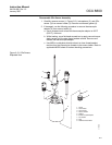
8. Install and fasten thermocouple (8, Figure 6-15).
9. Position band heater as shown in Figure 6-17 and Figure 6-18 and
tighten band heater clamp screw. The heater insulator (9) end joint must
line up with the band gap of the COe band heater (10).
37390058
0.37 in.
(9,4 mm)
COe Sensor
Band Heater
Insulator
The heater insulator prevents current leakage between the band heater and the sensor
holder. Failure to properly install the insulator may cause the device to trip a ground fault
interrupt circuit.