


Instruction Manual
IM-106-880, Rev 1.0
January 2007
OCX 8800
B-2
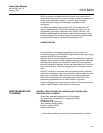
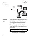
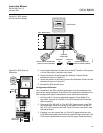
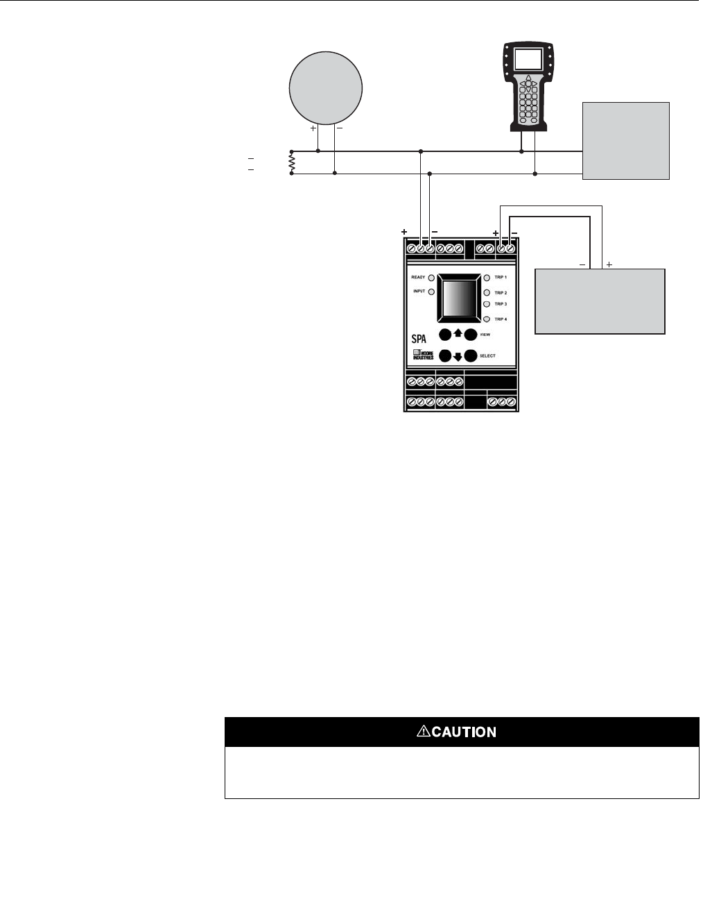
Figure B-2. OCX 8800 and
SPA Interface Connections
INSTALLATION Refer to Figure B-2 for the typical interface connections for the OCX 8800 and
the SPA with HART alarm. Refer to the Moore Industries SPA user's manual
for additional information concerning SPA installation, setup, and operation.
SETUP Setup of the SPA for communication with the OCX 8800 includes setting
internal jumpers and dip switches and configuring the SPA operating
parameters via a menu-driven selection and calibration procedure.
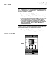
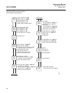
Jumper and Switch Settings
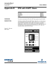
SPA jumper and switch settings are shown in Figure B-3. If the SPA with
HART was factory-configured by Emerson Process Management for
operation with your OCX 8800, jumper and switch setting adjustments are not
required. However, you may use the following procedure to verify that the
jumper and switch settings are correct. Adjust or verify jumper and switch
settings as follows:
1. Refer to Figure B-3. Turn the SPA over and slide the access cover out.
Before changing any jumper or switch position, take adequate
precautions to avoid an electrostatic discharge.
HART
Model 275/375
Handheld
Communicator
Analog Output
IN IN
4-20 mA
or
0-24 vdc
4-20 mA O Signal Loop
2
37390022
250
950
>
<
R
Ω
Ω
OCX 8800
Customers
DCS, PLC,
or
PC with AMS
Software
Event Recorder,
Audible Alarm,
or other
Analog Device
Electrostatic discharge (ESD) protection is required to avoid damage to the SPA electronic
circuits.