


Instruction Manual
IM-106-880, Rev 1.0
January 2007
OCX 8800
1-6
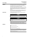
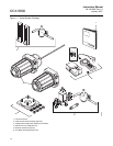
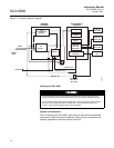
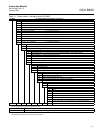
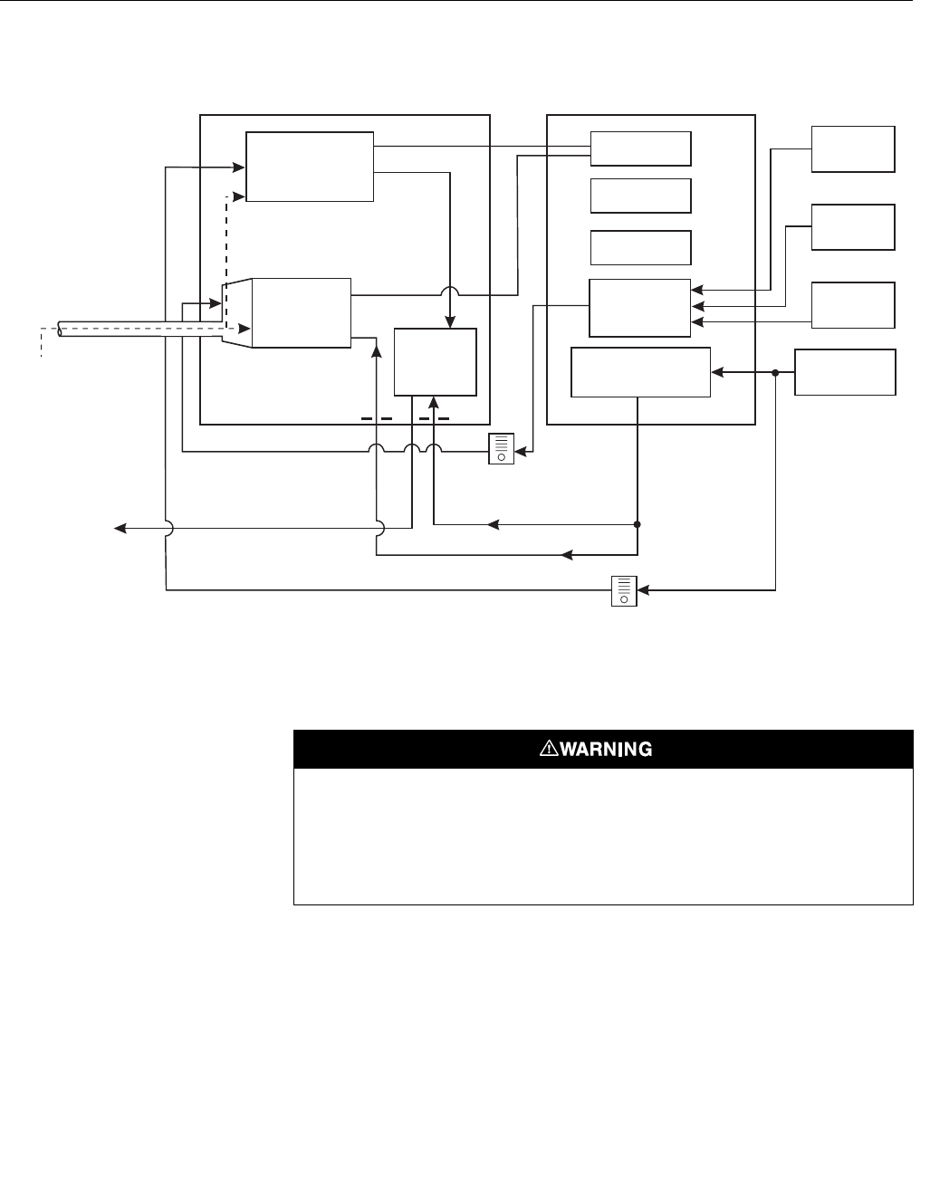
Figure 1-2. System Operation Diagram
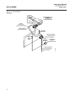
Handling the OCX 8800
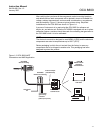
System Considerations
Prior to installing your OCX 8800, make sure you have all the components
necessary to make the system installation. Ensure all the components are
properly integrated to make the system functional.
Low O
Test Gas
2
COe
Combustibles
Sensor
O
Sensor
2
Eductor
Probe
Exhaust
CPU
HART
Board
Optional
Test Gas
Solenoids
Instrument Air
Solenoid
High O
Test Gas
2
CO
Test Gas
Instrument
Air
Dilution Air
Reference Air
Eductor Air
Flow Meter
50 cc/min.
(
0.1 scfh
)
SENSOR
HOUSING
ELECTRONICS
HOUSING
Flow Meter
7 scfh
37390001
Sample
Gas
Power
Supply
It is important that printed circuit boards and integrated circuits are handled only when
adequate antistatic precautions have been taken to prevent possible equipment damage.
The OCX 8800 is designed for industrial application. Treat each component of the system
with care to avoid physical damage. The probe may contain components made from
ceramics, which are susceptible to shock when mishandled.