


Instruction Manual
IM-106-880, Rev 1.0
January 2007
6-19
OCX 8800
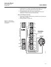
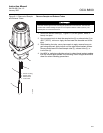
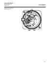
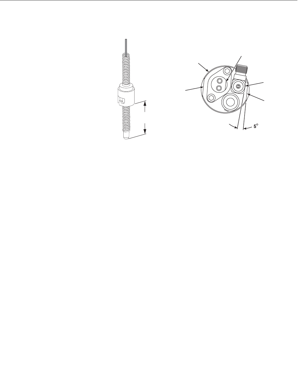
Figure 6-14. COe Sensor and
Pre-Heater Alignment
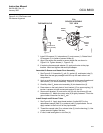
7. Install COe sensor (3), lockwashers (2), and screws (1). Rotate flat of
COe sensor (3) to center of sensor holder (4).
8. Align COe sensor flat parallel to sensor holder flat, as shown in
Figure 6-14. Tighten screws (1, Figure 6-13).
9. If replacing thermocouple adaptor (6), apply anti-seize to the pipe
threads. Install and tighten thermocouple adaptor.
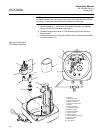
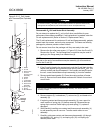
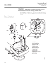
Assemble O
2
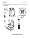
Sensor and Heater Strut Assembly
1. See Figure 6-12. Assemble O
2
cell (2), gasket (5), and heater tube (3).
Make sure the test gas passage holes line up with each other in all
components.
2. Apply a small amount of anti-seize compound to the screw threads and
use screws (1) to secure assembly. Torque to 35 in-lbs (4 N·m).
3. Carefully slide O
2
heater strut assembly (9) into heater tube (3).
4. Press down on the back plate of strut bracket (12) to ensure spring (11)
tension is present to hold contact pad against O
2
cell (2).
5. Secure strut bracket (12) and return wire (8) with four screws (6) and
lockwashers (7). Make sure return wire (8) is tightly fastened. This is the
ground side connection for the O
2
cell.
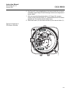
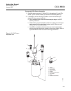
Install Sample and Exhaust Tubes
1. See Figure 6-11. Apply pipe thread sealant (Loctite #567) to the
replacement sample tube (2) or exhaust tube (3) pipe threads. Do not
apply sealant to the first turn of the pipe threads.
2. Thread the sample tube (2) or exhaust tube (3) into the housing (1). Use
a pipe wrench to tighten the tube.
3. If used, install and tighten in-situ filter (4).
37390034
Pre-Heater
Flat
COe
SENSOR ASSEMBLY
TOP VIEW
Sensor
Holder
Flat
COe Sensor
Flat
Sensor
Holder
Flat
Sensor
Holder
2 to 2-1/4 in.
(51 to 57 mm)
THERMOCOUPLE